


Mikroelektronika d.o.o.
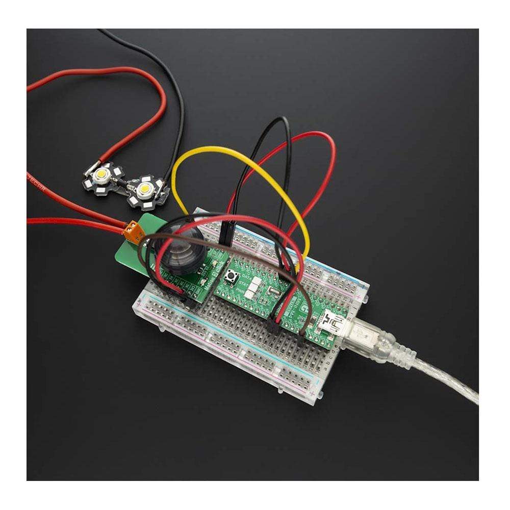
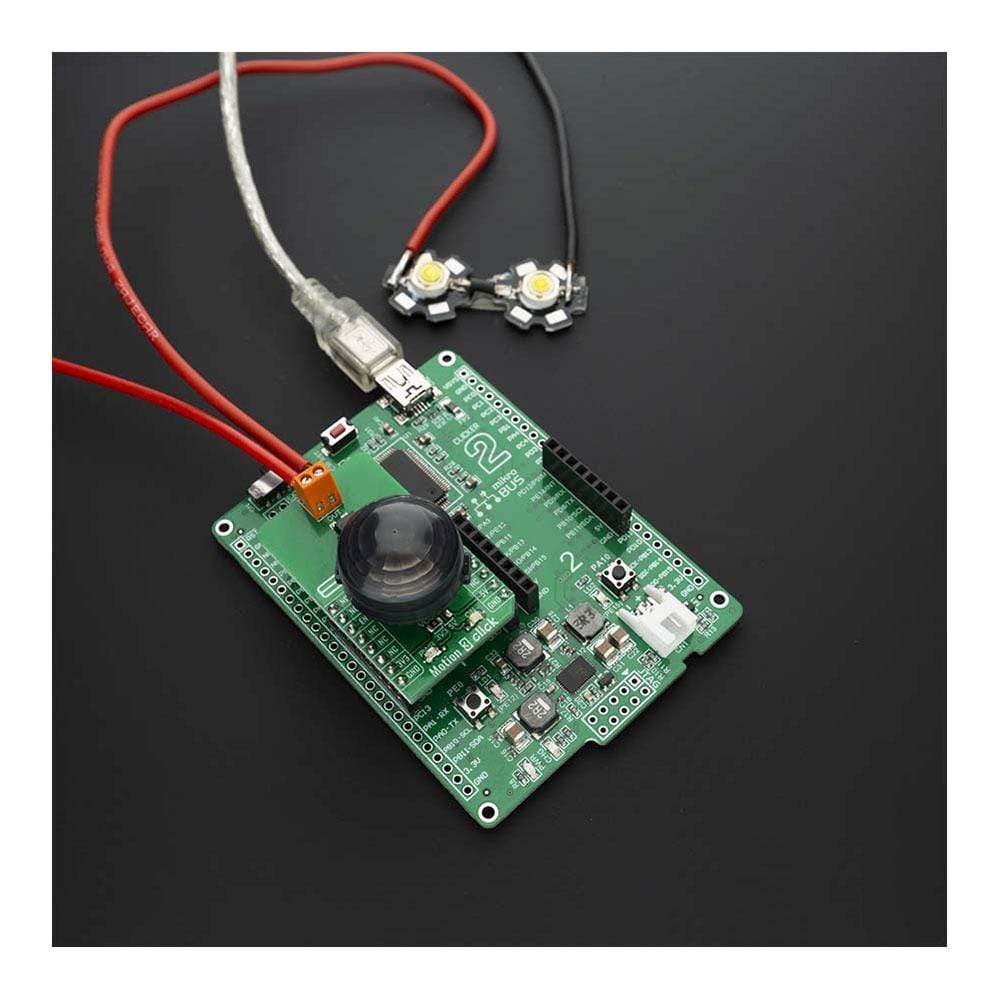
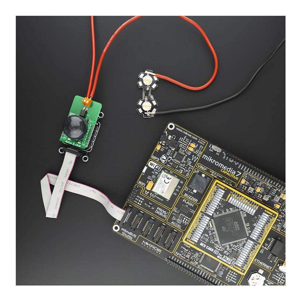
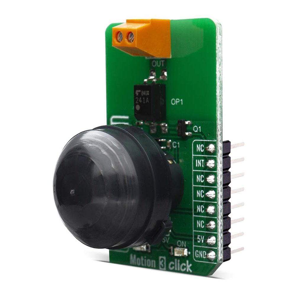
Motion 3 Click Board™
Motion 3 Click Board™
SKU: MIKROE-4049
Couldn't load pickup availability


Overview
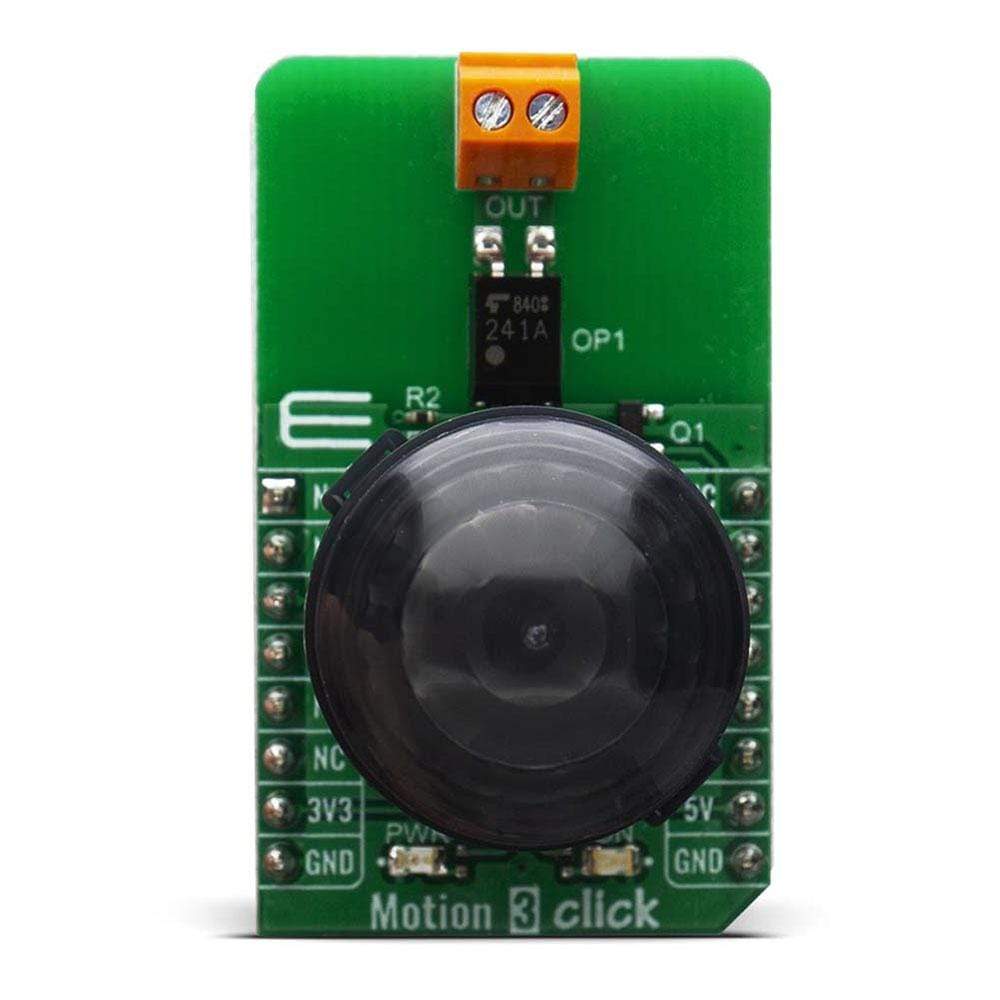
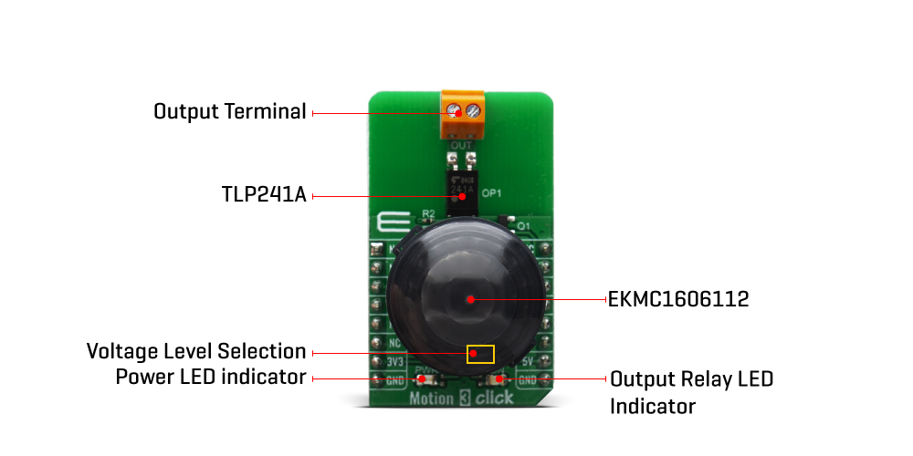
The Motion 3 Click Board™ is based on EKMC1606112, a PIR motion sensor from Panasonic Corporation that's used as a human motion detector. Also featured on the Motion 3 Click Board™ is the TLP241A photo relay from Toshiba that is used to provide reinforced galvanic isolation for the external signals used to drive some external high power electronic equipment when motion is detected. It's allowing up to 40V between the SSR contacts in the OFF state, and currents up to 2A while in the ON state, thanks to a very low ON-state resistance.
The Motion 3 Click Board™ is supported by a mikroSDK compliant library, which includes functions that simplify software development. This Click Board™ comes as a fully tested product, ready to be used on a system equipped with the mikroBUS™ socket.
Downloads
How Does The Motion 3 Click Board™ Work?
The Motion 3 Click Board™ is using a PIR sensor that can detect changes in the amount of infrared radiation impinging upon it, which varies depending on the temperature and surface characteristics of the objects in front of the sensor. Detection performance of EKMC1606112 at ambient temperature of 25℃ with temperature difference of 8℃ is up to 17m and for temperature difference of 4℃ it's up to 12m. Angle detection area with 128 detection zones is 62°(±31°)horizontal and 62°(±31°)vertical.
Output from PIR sensor is feed into buffer and then photo-relay allowing users to directly control with galvanic isolation from sensor and MCU electronic devices such as lights, motors, gates etc. The TLP241A photo-relay is able to effectively replace traditionally used mechanical relays, bringing up the full set of inherited benefits: virtually unlimited number of cycles since there are no moving parts that would wear off, no bouncing effect on the output contacts, high resistance to mechanical shock and environmental influence, low current required for the activation, constant resistance since no carbon and rust can build up on contacts, there is no sparking or electric arc forming while operated, compact size, higher isolation voltage, and so on.
When an object, such as a person, passes in front of the background, such as a wall, the temperature at that point in the sensor's field of view will rise from room temperature to body temperature, and then back again. The sensor converts the resulting change in the incoming infrared radiation into a change in the output voltage, and this triggers the detection. Objects of similar temperature but different surface characteristics may also have a different infrared emission pattern, and thus moving them with respect to the background may trigger the detector as well. In some cases, going back and forth towards the sensor (parallel movement to the axis Z), may not be detected.
Difficulty in sensing the heat source is that glass, acrylic or similar materials standing between the target and the sensor may not allow a correct transmission of infrared rays and also non-movement or quick movements of the heat source inside the detection area.
SPECIFICATIONS
| Type | Motion |
| Applications | Alarm systems, light switch controllers, automatic doors and similar systems where human presence needs to be detected. |
| On-board modules | EKMC1606112 the PIR motion sensor |
| Key Features | 128 detection zones, wide detection range and maximum range between 12 and 17 m |
| Interface | GPIO |
| Compatibility | mikroBUS |
| Click board size | M (42.9 x 25.4 mm) |
| Input Voltage | 3.3V or 5V |
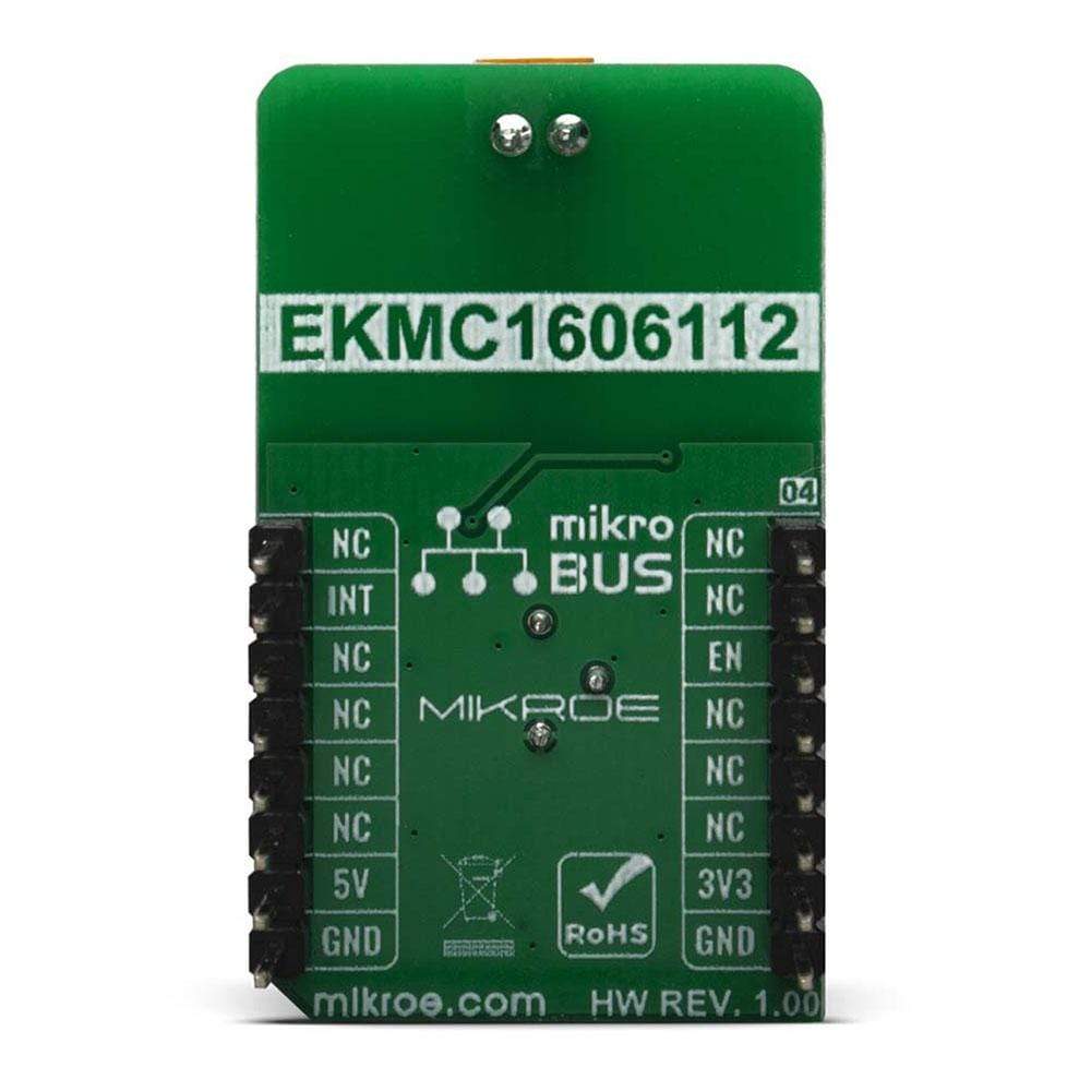
PINOUT DIAGRAM
This table shows how the pinout of the Motion 3 Click Board™ corresponds to the pinout on the mikroBUS™ socket (the latter shown in the two middle columns).
| Notes | Pin | Pin | Notes | ||||
|---|---|---|---|---|---|---|---|
| NC | 1 | AN | PWM | 16 | NC | ||
| NC | 2 | RST | INT | 15 | INT | Interrupt | |
| Enable | EN | 3 | CS | RX | 14 | NC | |
| NC | 4 | SCK | TX | 13 | NC | ||
| NC | 5 | MISO | SCL | 12 | NC | ||
| NC | 6 | MOSI | SDA | 11 | NC | ||
| Power Supply | 3.3V | 7 | 3.3V | 5V | 10 | 5V | Power Supply |
| Ground | GND | 8 | GND | GND | 9 | GND | Ground |
ONBOARD SETTINGS AND INDICATORS
| Label | Name | Default | Description |
|---|---|---|---|
| PWR | LD1 | - | Power LED Indicator |
| ON | LD2 | - | Photorelay ON Indicator |
| JP1 | VCC SEL | Left | Logic voltage level selection: left position 3.3V, right position 5V |
DETECTION PERFORMANCE AND ELECTRICAL CHARACTERISTICS
| Temperature Difference | Value | |
|---|---|---|
| Detection Range | 8℃ | up to 17m |
| 4℃ | up to 12m | |
| Detection Area | Detection Angle | Value |
| Horizontal | 62°(±31°) | |
| Vertical | 62°(±31°) | |
| Detection Zones | 128 | |
| Photorelay Characteristics | Maximum Voltage | Maximum Current |
| 40V | 2A |
| General Information | |
|---|---|
Part Number (SKU) |
MIKROE-4049
|
Manufacturer |
|
| Physical and Mechanical | |
Weight |
0.02 kg
|
| Other | |
EAN |
8606018717132
|
Frequently Asked Questions
Have a Question?
Be the first to ask a question about this.