


Mikroelektronika d.o.o.
6DOF IMU 6 Click Board™
6DOF IMU 6 Click Board™
SKU: MIKROE-4044
Couldn't load pickup availability


Overview
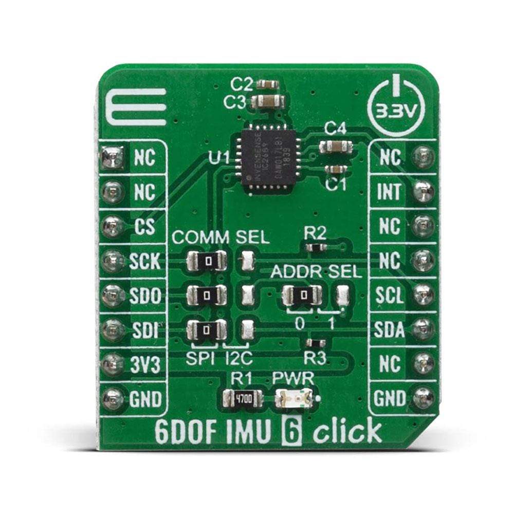
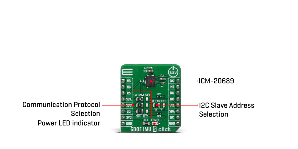
The 6DOF IMU 6 Click Board™ features a 6-axis motion tracking device that combines a 3-axis gyroscope, a 3-axis accelerometer, and a Digital Motion Processor™ (DMP) labelled as ICM-20689. The ICM-20689 from company TDK InvenSense includes on-chip 16-bit ADCs, programmable digital filters, an embedded temperature sensor, and programmable interrupts.
The gyroscope and accelerometer are full-scale range, user-programmable sensors with factory-calibrated initial sensitivity for reduced production-line calibration requirements.
Downloads
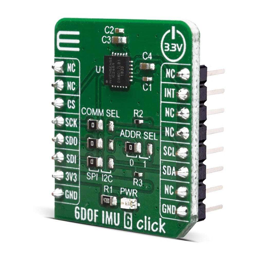
How Does The 6DOF IMU 6 Click Board™ Work?
The 6DOF IMU 6 Click Board™ uses ICM-20689, a 6-axis MotionTracking device that combines a 3-axis gyroscope, a 3-axis accelerometer, and a Digital Motion Processor™ (DMP) in a small 4x4x0.9mm (24-pin QFN) package. It also features a 4 Kbyte FIFO that can lower the traffic on the serial bus interface, and reduce power consumption by allowing the system processor to burst read sensor data and then go into a low-power mode.The ICM-20689, with its 6-axis integration, on-chip DMP, and run-time calibration firmware, enables manufacturers to eliminate the costly and complex selection, qualification, and system level integration of discrete devices, guaranteeing optimal motion performance.
The gyroscope has a programmable full-scale of ±250, ±500, ±1000, and ±2000 degrees/sec. The accelerometer has a user-programmable accelerometer full-scale range of ±2g, ±4g, ±8g, and ±16g. Factory-calibrated initial sensitivity of both sensors reduces production-line calibration requirements. Other industry-leading features include on-chip 16-bit ADCs, programmable digital filters, an embedded temperature sensor, and programmable interrupts. The device provides high robustness by supporting 10,000g shock reliability.
The device features I2C and SPI serial interfaces, wide operating voltage range (VDD) and separate digital IO supply (VDDIO) from 1.71V to 3.45V. Communication with all registers of the device can be performed using either I2C at 400kHz or SPI at 8MHz.
The 6DOF IMU 6 Click Board™ supports both SPI and I2C communication interfaces, allowing it to be used with a wide range of different MCUs. The communication interface can be selected by moving SMD jumpers grouped under the COM SEL to an appropriate position (SPI or I2C). The slave I2C address can also be configured by an SMD jumper when the Click board™ is operated in the I2C mode. An SMD jumper labeled as ADD SEL is used to set the least significant bit (LSB) of the I2C address.
Excellent choices for applications include mobile phones, tablets, drones, handset and portable gaming, motion-based game controllers, wearable sensors for health, fitness and sports and 3D remote controls for internet-connected DTVs and set-top boxes and 3D mice.
Specifications
| Type | Acceleration,Gyroscope,Motion |
| Applications | Excellent choices for applications include mobile phones, tablets, drones, handset and portable gaming, motion-based game controllers, wearable sensors for health, fitness and sports and 3D remote controls for internet-connected DTVs and set-top boxes and 3D mice |
| On-board modules | ICM-20689, a 6-axis MotionTracking device that combines a 3-axis gyroscope, a 3-axis accelerometer, and a Digital Motion Processor™ (DMP), from TDK InvenSense |
| Key Features | Includes on-chip 16-bit ADCs, programmable digital filters, an embedded temperature sensor, and programmable interrupts. |
| Interface | I2C,SPI |
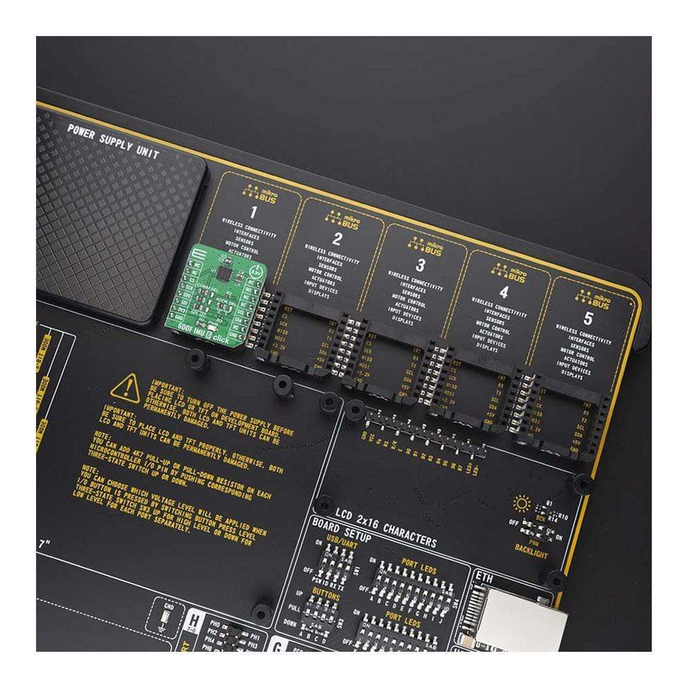
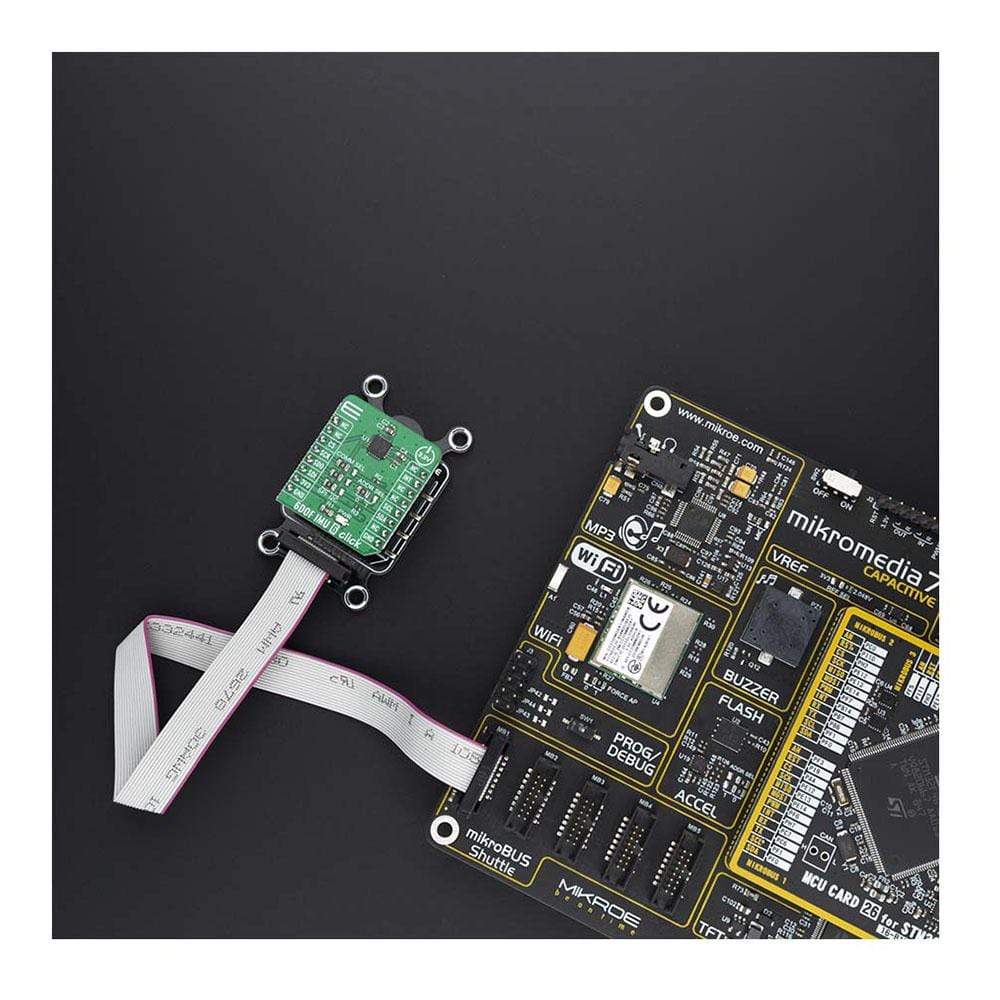
| Compatibility | mikroBUS |
| Click board size | S (28.6 x 25.4 mm) |
| Input Voltage | 3.3V |
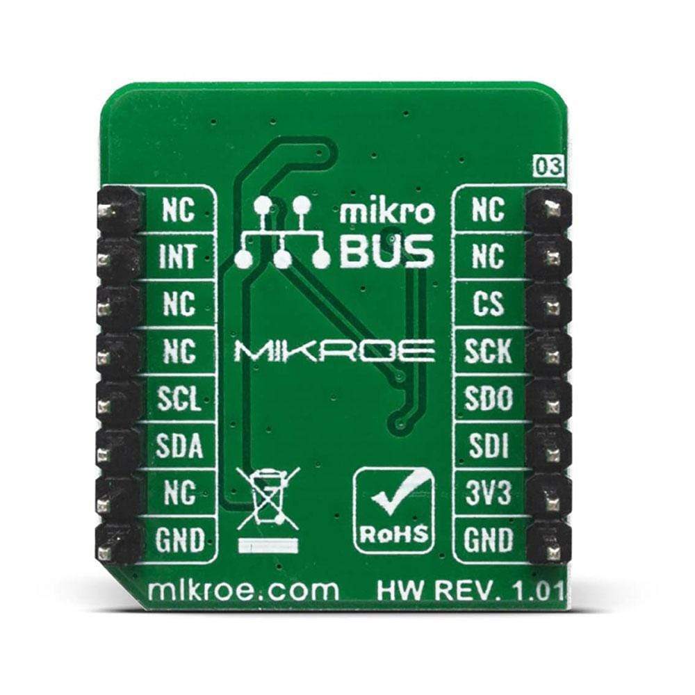
Pinout diagram
This table shows how the pinout on the 6DOF IMU 6 Click Board™ corresponds to the pinout on the mikroBUS™ socket (the latter shown in the two middle columns).
| Notes | Pin | Pin | Notes | ||||
|---|---|---|---|---|---|---|---|
| NC | 1 | AN | PWM | 16 | NC | ||
| NC | 2 | RST | INT | 15 | INT | Interrupt | |
| SPI Chip Select | CS | 3 | CS | RX | 14 | NC | |
| SPI Clock | SCK | 4 | SCK | TX | 13 | NC | |
| SPI Data OUT | SDO | 5 | MISO | SCL | 12 | SCL | I2C Clock |
| SPI Data IN | SDI | 6 | MOSI | SDA | 11 | SDA | I2C Data |
| Power Supply | 3.3V | 7 | 3.3V | 5V | 10 | NC | |
| Ground | GND | 8 | GND | GND | 9 | GND | Ground |
Onboard settings and indicators
| Label | Name | Default | Description |
|---|---|---|---|
| LD1 | PWR | - | Power LED Indicator |
| JP1-JP3 | COM SEL | Left | Communication interface selection: left position SPI, right position I2C |
| JP4 | ADD SEL | Left | Slave address LSB selection: left position 0, right position 1 |
| General Information | |
|---|---|
Part Number (SKU) |
MIKROE-4044
|
Manufacturer |
|
| Physical and Mechanical | |
Weight |
0.016 kg
|
| Other | |
EAN |
8606018717088
|
Frequently Asked Questions
Have a Question?
Be the first to ask a question about this.