


Mikroelektronika d.o.o.
RS232 SPI Click Board™
RS232 SPI Click Board™
SKU: MIKROE-3912
Couldn't load pickup availability


Overview
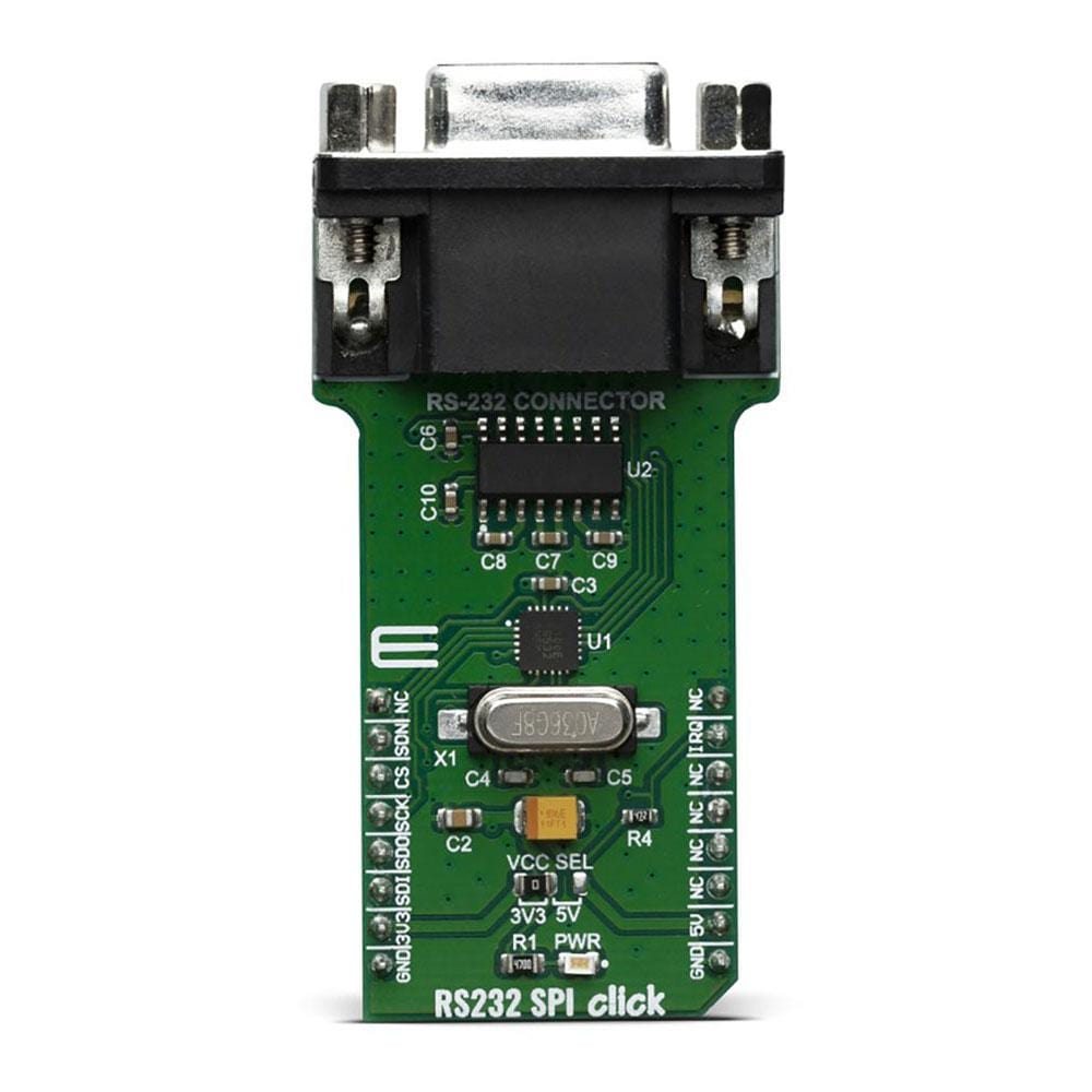
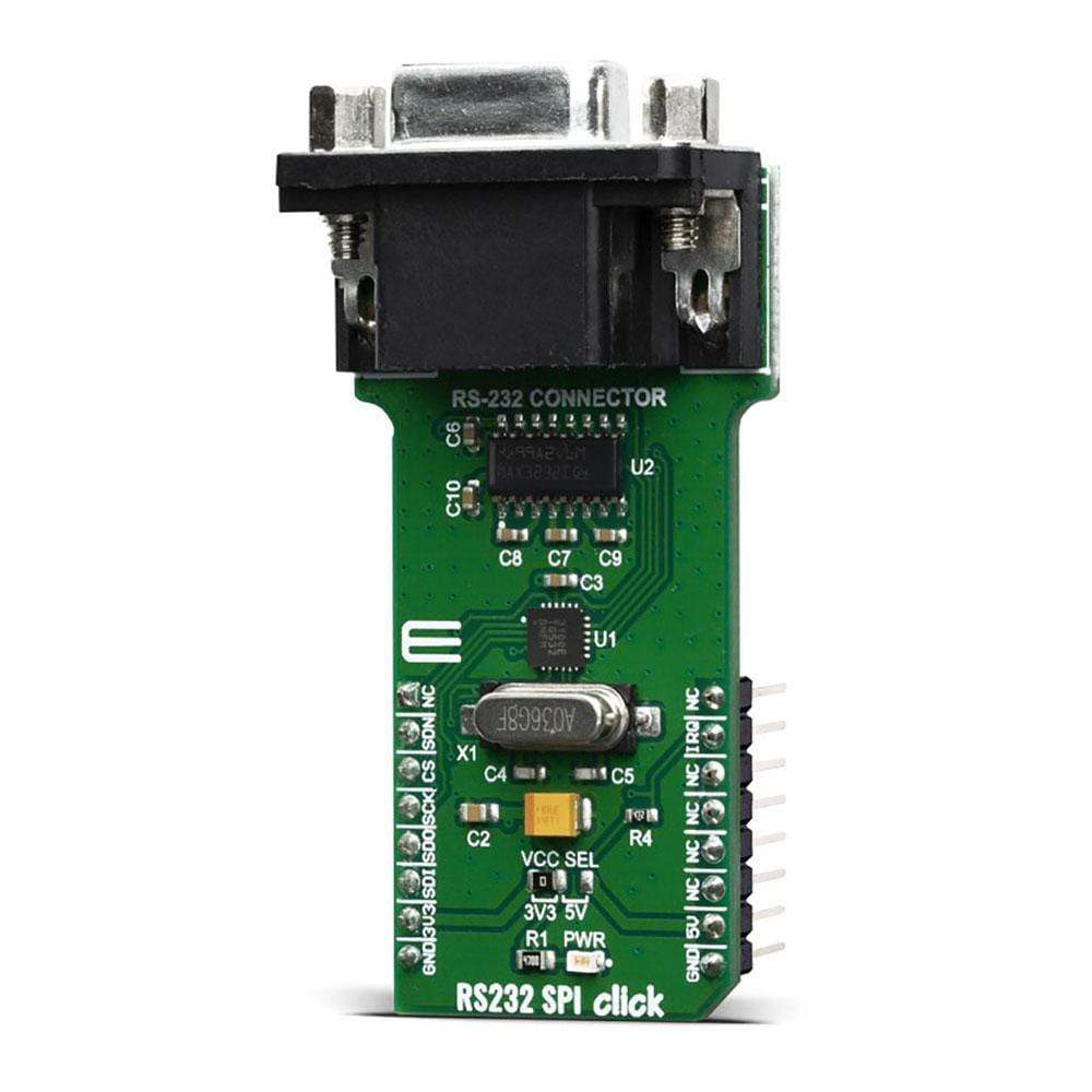
The RS232 SPI Click Board™ is based around the MAX3100, a universal asynchronous receiver transmitter (UART) - the first UART optimised explicitly for small microcontroller-based systems, from Maxim Integrated. Because of the features contained in its modules, the RS232 SPI Click Board™ can be used for handheld instruments, small networks in HVAC or Building control, UART in SPI systems, battery-powered systems, PDAs, notebooks and many more.
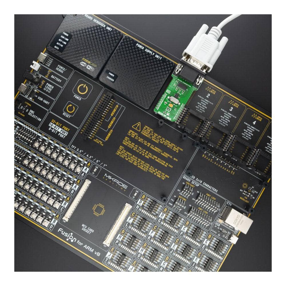
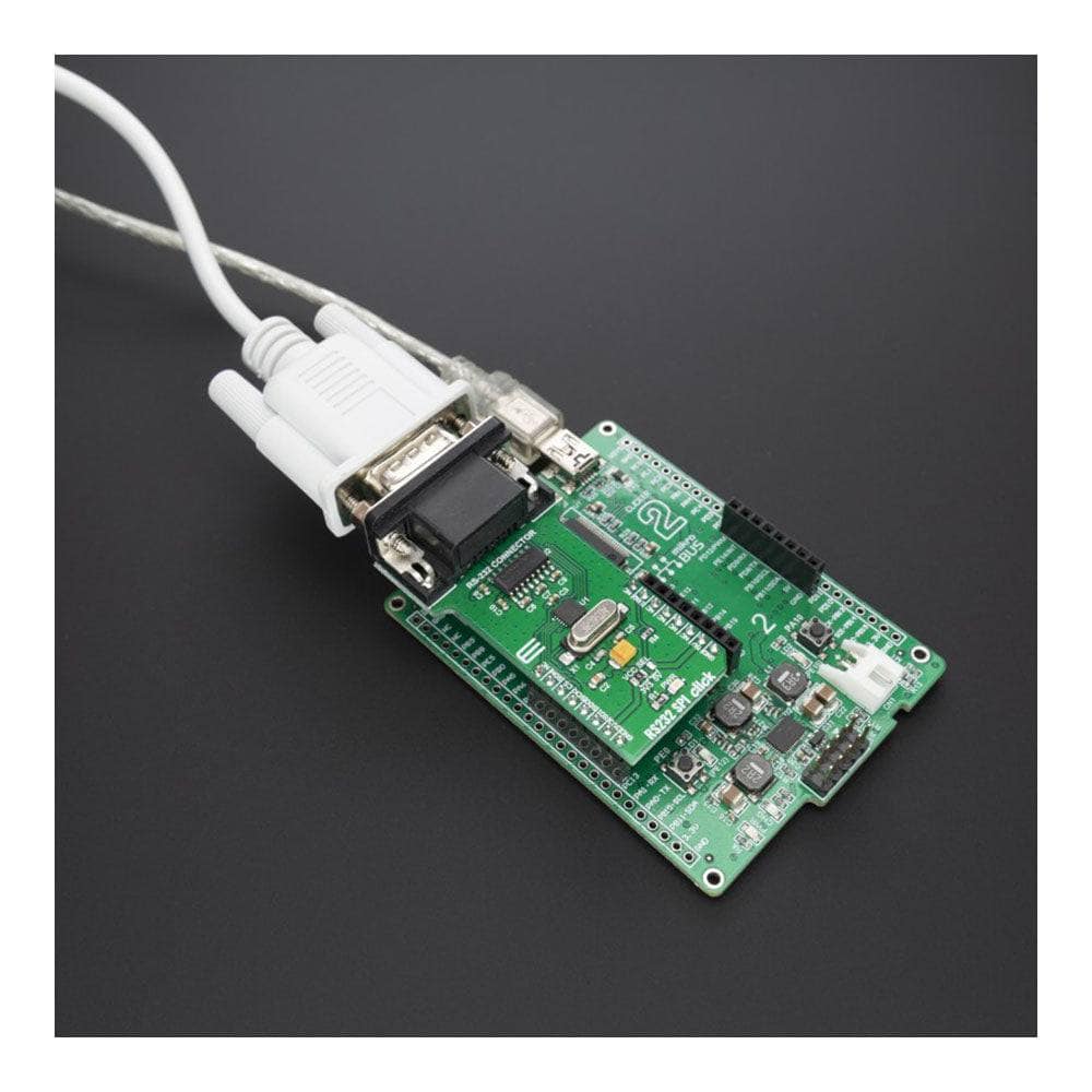
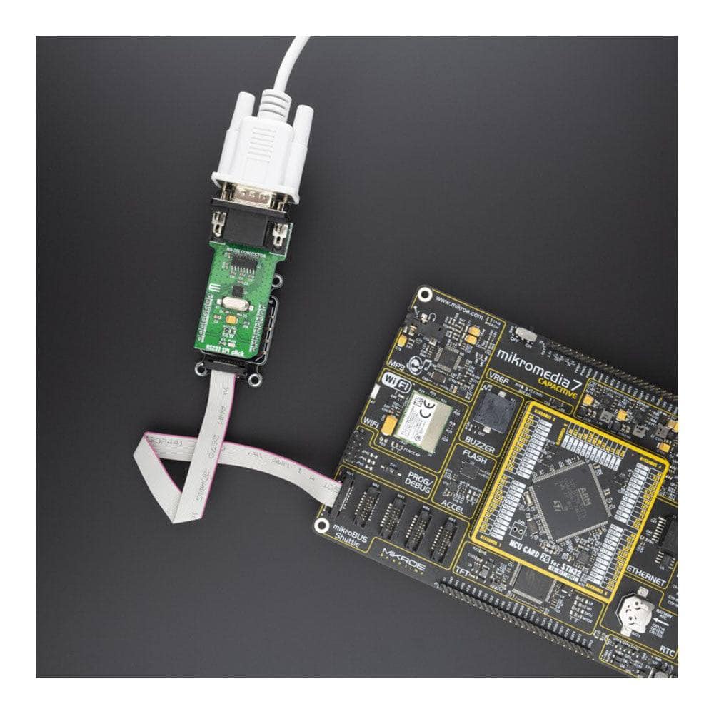
The RS232 SPI Click Board™ is supported by a mikroSDK compliant library, which includes functions that simplify software development. This Click Board™ comes as a thoroughly tested product, ready to be used on a system equipped with the mikroBUS™ socket.
Downloads
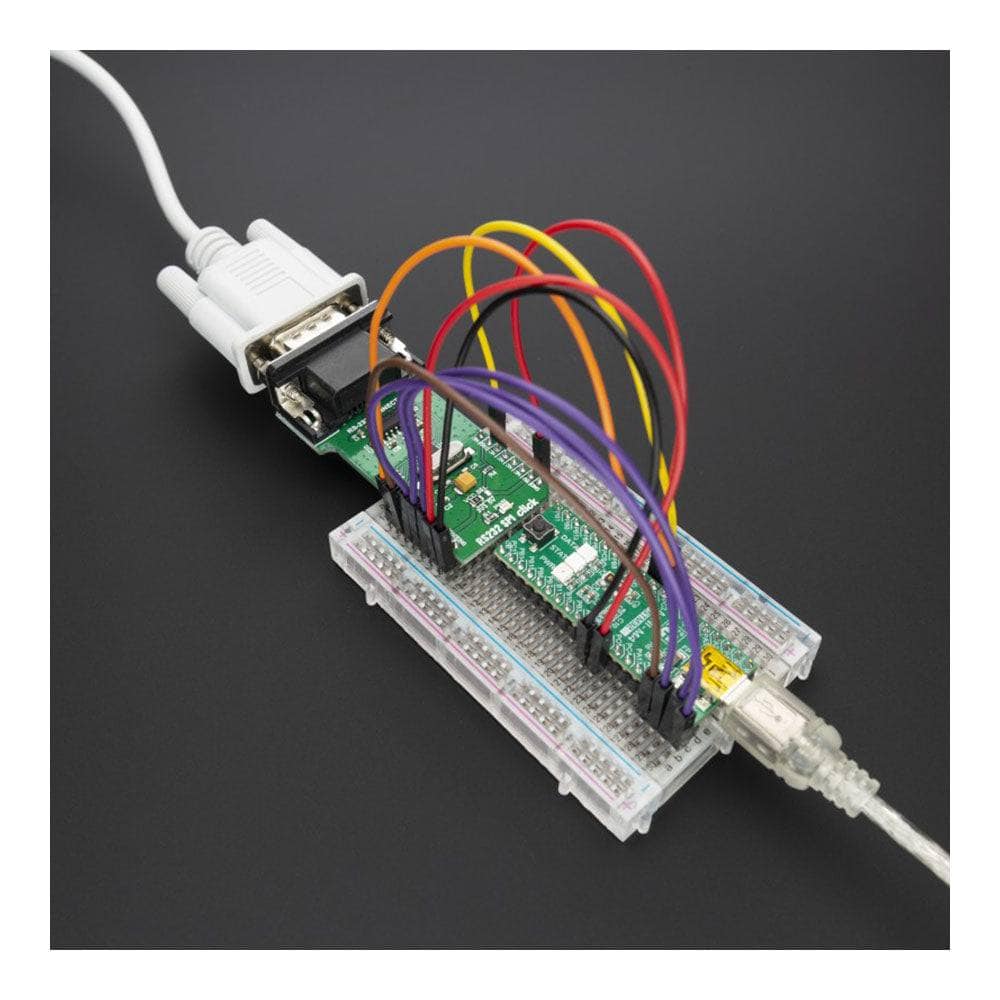
How Does The RS232 SPI Click Board™ Work?
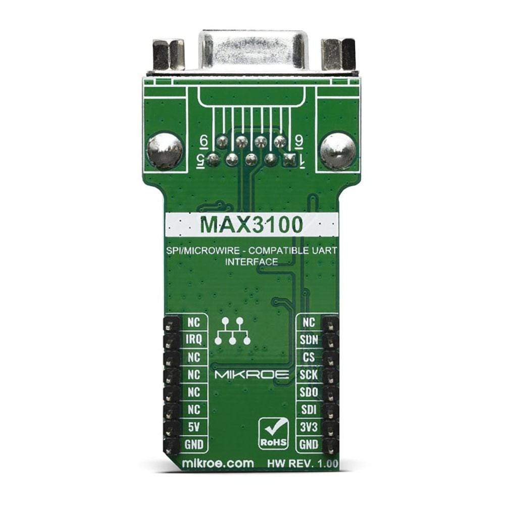
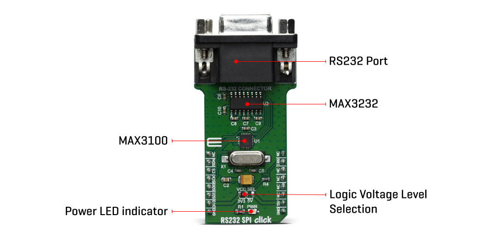
The RS232 SPI Click Board™ uses two ICs - MAX3100 and MAX3232. MAX3100 serves as UART interface to the SPI/MICROWIRE compatible interface converter. In the same time, MAX3232 device enables RS232 SPI click to meet the requirements of TIA/EIA-232-F and also provides the electrical interface between an asynchronous communication controller and the serial-port connector. The charge pump and four small external capacitors allow operation from a single 3-V to 5.5-V supply.
The RS232 SPI Click Board™ Uses an SPI™/MICROWIRE™ interface for communication with the host microcontroller (µC). Then, the MAX3100 is responsible for conversion from synchronous serial data from a microcontroller to asynchronous, serial-data communication port such as RS-232, RS-485, IrDA. In this case the RS232 protocol is used. The MAX3100 includes a crystal oscillator and a baud rate generator with software-programmable divider ratios for all common baud rates from 300 baud to 230k baud. The transmitter section accepts SPI/MICROWIRE data, formats it, and transmits it in asynchronous serial format from the TX output. Data is loaded into the transmit buffer register from the SPI/MICROWIRE interface. The MAX3100 adds start and stop bits to the data and clocks the data out at the selected baud rate.
A software- or hardware-invoked shutdown lowers quiescent current to 10µA, while allowing the MAX3100 to detect receiver activity. An 8-word-deep first-in/first-out (FIFO) buffer minimizes processor overhead. This device also includes a flexible interrupt with four maskable sources, including address recognition on 9-bit networks. Two hardware-handshaking control lines are included (one input and one output).
Because of the features contained in its modules, the RS232 SPI click can be used for handheld instruments, UART in SPI systems, small networks in HVAC or Building control, battery-powered systems, PDAs, notebooks and many more.
The RS232 SPI Click Board™ offers a selection between 3.3V and 5V operation, with the onboard SMD jumper, labelled as VCC SEL. This allows both 3.3V and 5V MCUs to be interfaced with this Click board™.
SPECIFICATIONS
| Type | RS232 |
| Applications | Handheld instruments, UART in SPI systems, small networks in HVAC or Building control, battery-powered systems, PDAs, notebooks and many more |
| On-board modules | MAX3100 MAX3100 serves as UART interface to the SPI/MICROWIRE compatible interface converter from Maxim Integrated; MAX3232, a 3-V to 5.5-V Multichannel RS-232 Line Driver/Receiver from Texas Instruments |
| Key Features | Operates up to 250 kbit/s, Operates With 3-V to 5.5-V VCC Supply, RS-232 Bus-Terminal ESD Protection Exceeds ±15 kV Using Human-Body Model (HBM) |
| Interface | SPI |
| Compatibility | mikroBUS |
| Click board size | L (57.15 x 25.4 mm) |
| Input Voltage | 3.3V or 5V |
PINOUT DIAGRAM
This table shows how the pinout of the RS232 SPI Click Board™ corresponds to the pinout on the mikroBUS™ socket (the latter shown in the two middle columns).
| Notes | Pin | Pin | Notes | ||||
|---|---|---|---|---|---|---|---|
| NC | 1 | AN | PWM | 16 | NC | ||
| Device shut down | SDN | 2 | RST | INT | 15 | INQ | Interrupt Output |
| SPI Chip Select | CS | 3 | CS | RX | 14 | NC | |
| SPI Clock | SCK | 4 | SCK | TX | 13 | NC | |
| SPI Data OUT | SDO | 5 | MISO | SCL | 12 | NC | |
| SPI Data IN | SDI | 6 | MOSI | SDA | 11 | NC | |
| Power Supply | 3.3V | 7 | 3.3V | 5V | 10 | 5V | Power supply |
| Ground | GND | 8 | GND | GND | 9 | GND | Ground |
ONBOARD SETTINGS AND INDICATORS
| Label | Name | Default | Description |
|---|---|---|---|
| LD1 | PWR LED | - | Power LED Indicator |
| JP1 | VCC SEL | Left | Power supply voltage selection: left position 3.3V, right position 5V |
| General Information | |
|---|---|
Part Number (SKU) |
MIKROE-3912
|
Manufacturer |
|
| Physical and Mechanical | |
Weight |
0.029 kg
|
| Other | |
EAN |
8606018719112
|
Frequently Asked Questions
Have a Question?
Be the first to ask a question about this.