


Mikroelektronika d.o.o.
H-Bridge 5 Click Board™
H-Bridge 5 Click Board™
SKU: MIKROE-3854
Couldn't load pickup availability
Overview
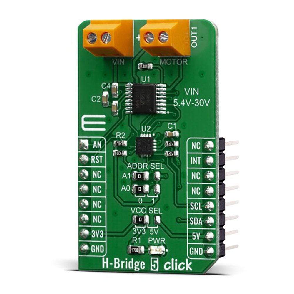
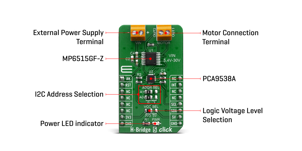
The H-Bridge 5 Click Board™ is designed for control DC motors and inductive loads. This Click Board™ contains the MP6515GF-Z, an H-bridge motor driver from MPS, It features a Full H-Bridge driver with Internal safety features include over-current protection, input over-voltage protection, under-voltage lockout (UVLO), and thermal shutdown. This Click Board™ also contains the PCA9538A, a low-voltage 8-bit General Purpose Input/Output (GPIO) expander.
The H-Bridge 5 Click Board™ can be used for Solenoid Drivers and DC Brush Motor drivers.
Downloads
How Does The H-Bridge 5 Click Board™ Work?
The H-Bridge 5 Click Board™'s most important and relevant feature is the MP6515GF-Z, a H-bridge motor driver from Monolithic Power Systems (MPS). This Click Board™ is operates from a supply voltage of up to 30V and delivers motor current up to 1.5A. Its main applications include Solenoid Drivers and DC Brush Motor Drive.
Its internal safety features include over-current protection, input over-voltage protection, undervoltage lockout (UVLO), and thermal shutdown. The MP6515GF-Z integrates four N-channel power MOSFETs with 2.8A peak current capability. It is designed to drive DC brush motors, solenoids, or other loads.
When it comes to current sensing, the current flowing in the two low-side MOSFETs is sensed with an internal current sensing circuit. A voltage that is proportional to the output current is sourced on VISEN. Current is sensed when one of the low-side MOSFETs is turned on, including during slow decay (brake) mode. The load current applied to VISEN should be kept below 2mA, with no more than 500pF of capacitance.
The H-Bridge 5 Click Board™ also contains the PCA9538A, a low-voltage 8-bit General Purpose Input/Output (GPIO) expander with interrupt and reset for I2C-bus/SMBus applications. This feature is designed by NXP. NXP I/O expanders provide a simple solution when additional I/Os are needed while keeping interconnections to a minimum. Expanders provide communication between MP6515GF-Z and MCU, MCU control expander with I2C communication, and set output logic level for I/O pins.
The PCA9538A is an I2C-bus slave device. Data is exchanged between the master and PCA9538A through write and read commands using I2C-bus. The two communication lines are a serial data line (SDA) and a serial clock line (SCL). Both lines must be connected to a positive supply via a pull-up resistor when connected to the output stages of a device. Data transfer may be initiated only when the bus is not busy. Given all the capabilities the features that are contained in the H-Bridge 5 Click Board™ have, this Click Board™ is best used for Solenoid Drivers and DC Brush Motor Drive.
The H-Bridge 5 Click Board™ comes with a mikroC, mikroBASIC, and mikroPASCAL compilers compatible library, which contains functions for easy and simple operating of this Click Board™. The provided example application demonstrates their usage and can be used as a reference for custom projects.
SPECIFICATIONS
| Type | Brushed |
| Applications | Solenoid Drivers and DC Brush Motor Drive |
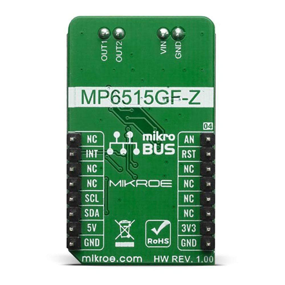
| On-board modules | MP6515GF-Z, a H-bridge motor driver from MPS |
| Key Features | Simple and versatile logic Interfaces, 3.3V and 5V Compatible Logic Supply, Internal Full H-Bridge Driver, Fault Indication Output |
| Interface | Analog,I2C |
| Compatibility | mikroBUS |
| Click Board™ size | M (42.9 x 25.4 mm) |
| Input Voltage | 3.3V or 5V |
PINOUT DIAGRAM
This table shows how the pinout on H-Bridge 5 Click Board™ corresponds to the pinout on the mikroBUS socket (the latter shown in the two middle columns).
| Notes | Pin | Pin | Notes | ||||
|---|---|---|---|---|---|---|---|
| Analog voltage output | AN | 1 | AN | PWM | 16 | NC | |
| Reset | RST | 2 | RST | INT | 15 | INT | Interrupt pin |
| NC | 3 | CS | RX | 14 | NC | ||
| NC | 4 | SCK | TX | 13 | NC | ||
| NC | 5 | MISO | SCL | 12 | SCL | I2C Clock | |
| NC | 6 | MOSI | SDA | 11 | SDA | I2C Data | |
| Power Supply | 3.3V | 7 | 3.3V | 5V | 10 | 5V | Power supply |
| Ground | GND | 8 | GND | GND | 9 | GND | Ground |
ONBOARD SETTINGS AND INDICATORS
| Label | Name | Default | Description |
|---|---|---|---|
| LD1 | PWR | - | Power LED Indicator |
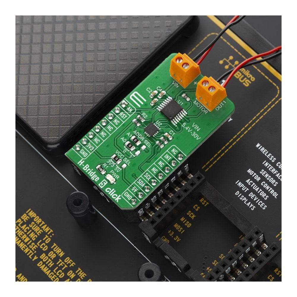
| TB1 | VIN | - | Terminal udes for connecting external input voltage |
| TB2 | MOTOR | - | Terminal used for connection motor |
| JP1 | VCC SEL | Left | Power supply voltage selection: left position 3.3V, right position 5V |
| JP2 | ADR0 | Left | Select I2C address bit |
| JP3 | ADR1 | Left | Select I2C address bit |
H-BRIDGE 5 Click Board™ ELECTRICAL SPECIFICATIONS
| Description | Min | Typ | Max | Unit |
|---|---|---|---|---|
| Receive input voltage range | 5.4 | - | 30 | V |
| Receive input current range | - | - | 1.5 | A |
| General Information | |
|---|---|
Part Number (SKU) |
MIKROE-3854
|
Manufacturer |
|
| Physical and Mechanical | |
Weight |
0.02 kg
|
| Other | |
EAN |
8606018719488
|
Frequently Asked Questions
Have a Question?
Be the first to ask a question about this.