


Mikroelektronika d.o.o.
GMR Angle Click Board™
GMR Angle Click Board™
SKU: MIKROE-3815
Couldn't load pickup availability


Overview
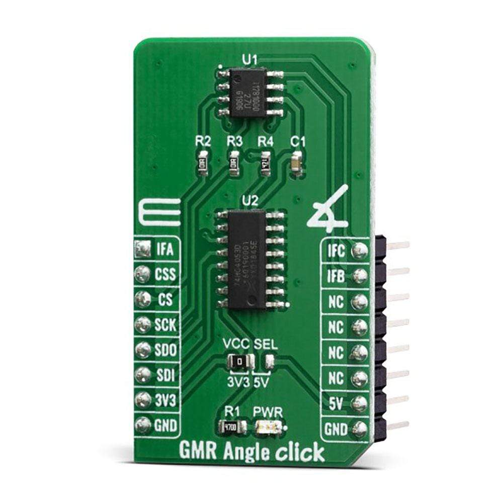
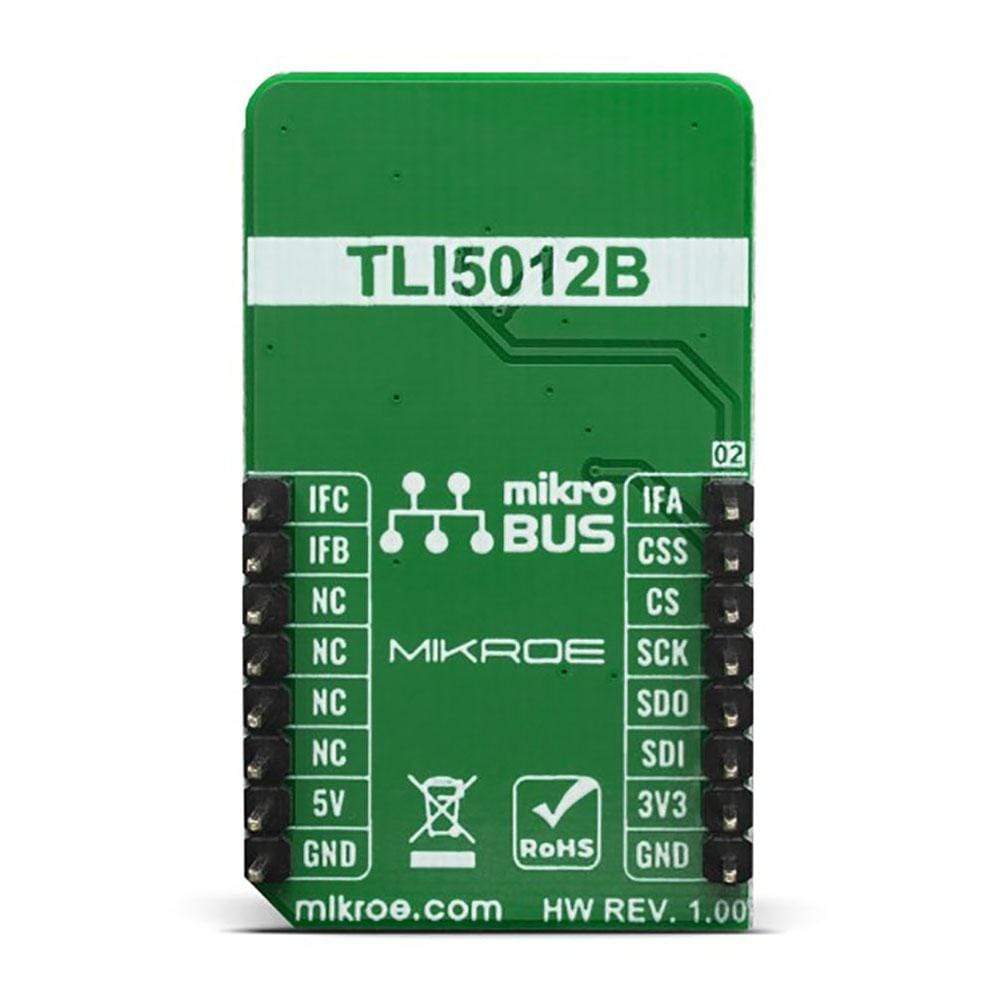
The GMR Angle Click Board™ features the TLI5012B E1000, which is a pre-calibrated 360° angle sensor that detects the orientation of a magnetic field, made by Infineon. The GMR Angle click is ideal for angular position sensing in industrial and consumer applications such as an electrically commutated motor (e.g. BLDC), fans or pumps.
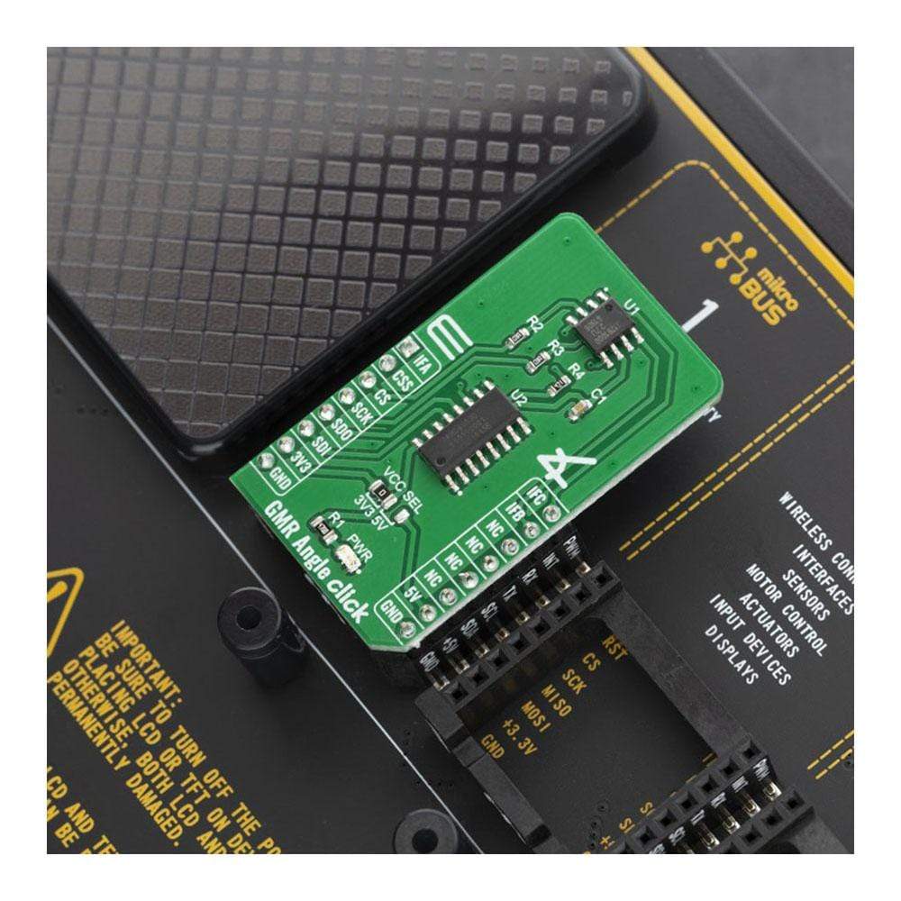
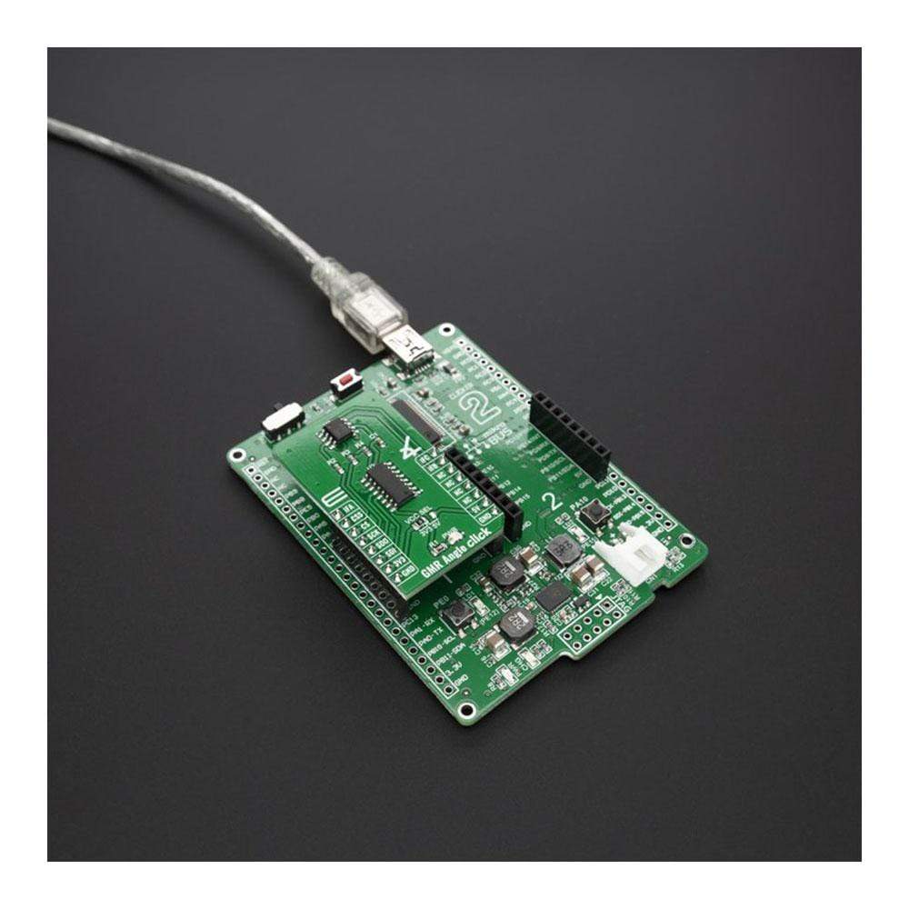
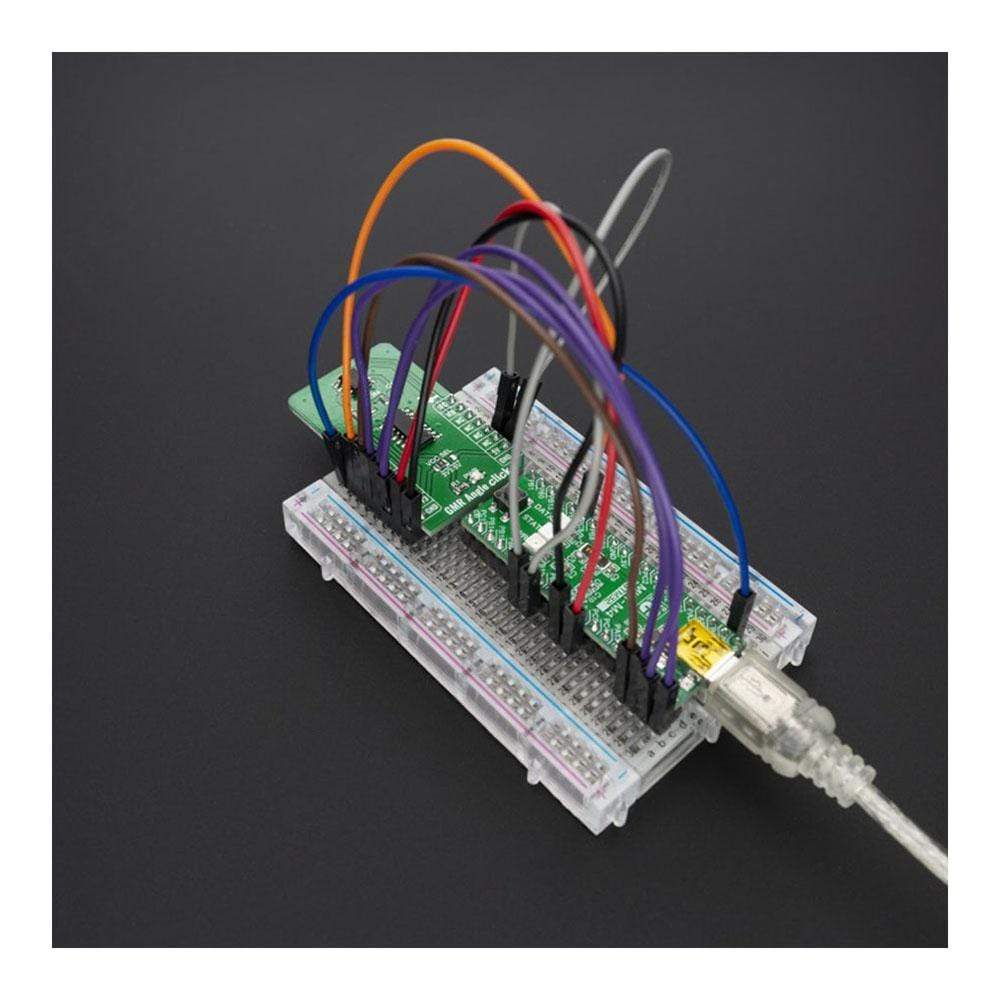
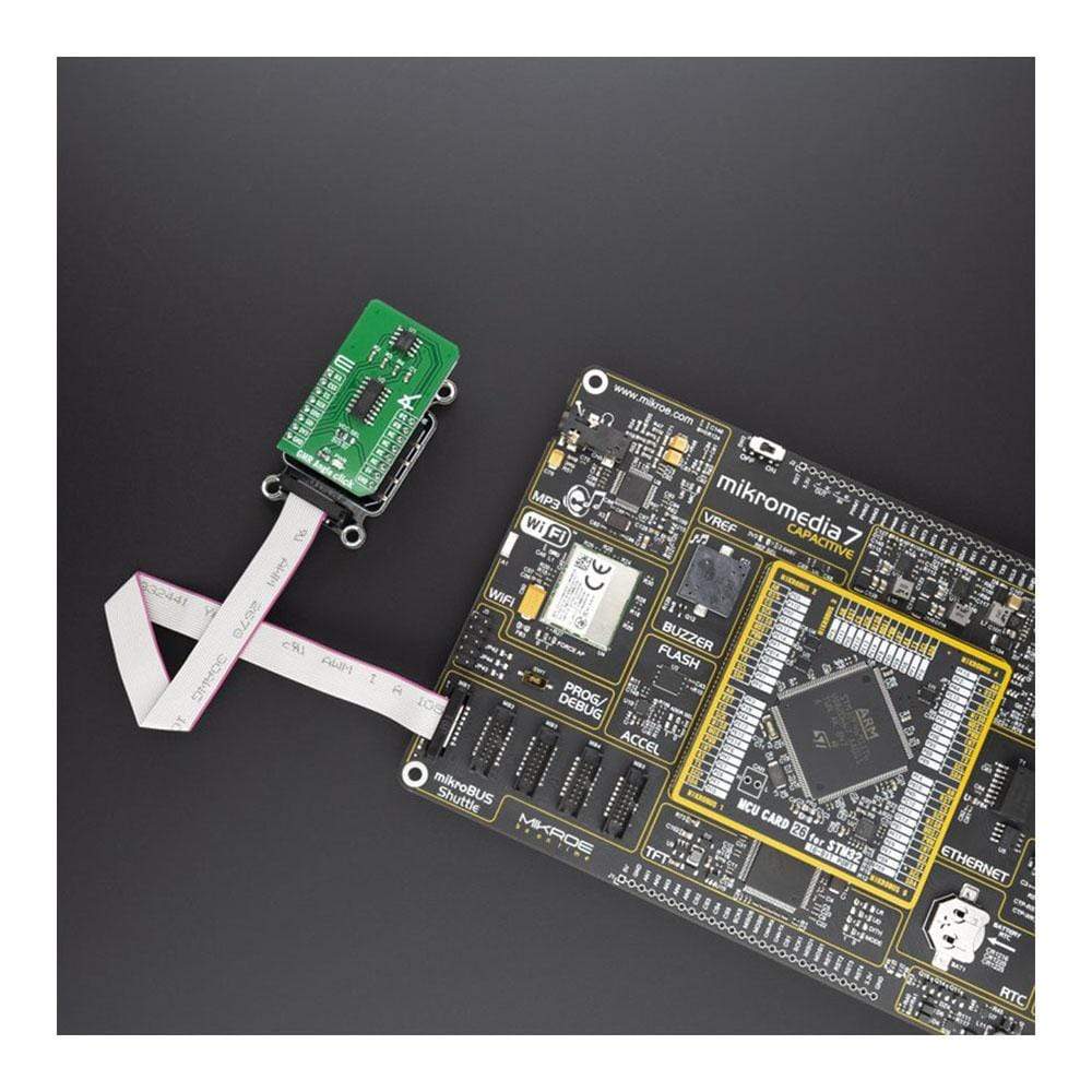
The GMR Angle click is supported by a mikroSDK compliant library, which includes functions that simplify software development. This Click Board™ comes as a fully tested product, ready to be used on a system equipped with the mikroBUS™ socket.
Downloads
How Does The GMR Angle Click Board™ Work?
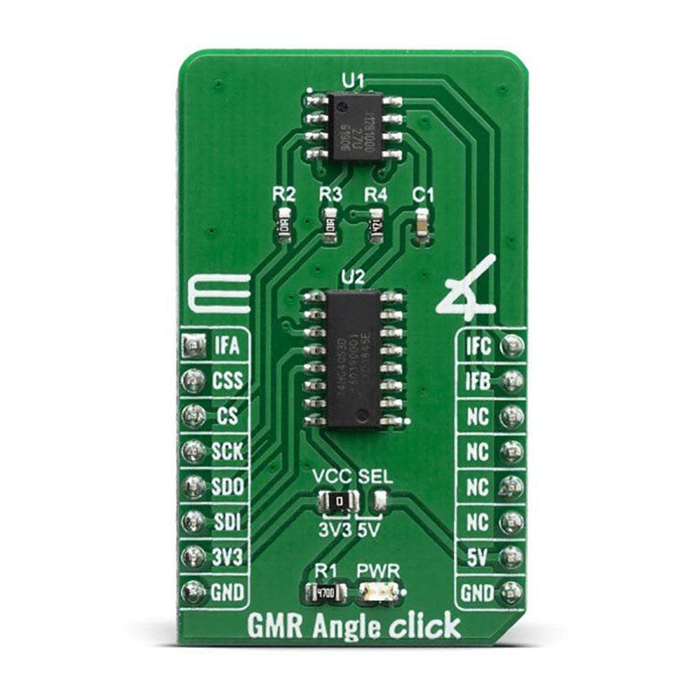
The GMR Angle Click Board™ contains the TLI5012B E1000 from Infineon Technologies AG, GMR-based is a 360° angle sensor, for detects any kind the orientation of a magnetic field, and the analog multiplexer 74HCT4053, switch a bi-directional Synchronous Serial Communication DATA line. This is achieved by measuring sine and cosine angle components with monolithic integrated Giant Magneto Resistance (iGMR) elements. These raw signals (sine and cosine) are digitally processed internally to calculate the angle orientation of the magnetic field (magnet).
.jpg)
The calibration parameters are stored in laser fuses. At start-up the values of the fuses are written into flip-flops, where these values can be changed by the application-specific parameters. Further precision of the angle measurement over a wide temperature range and a long lifetime are improved with the internal autocalibration algorithm.
The Giant Magneto Resistance (GMR) sensor is implemented using vertical integration. This means that the GMR-sensitive areas are integrated above the logic part of the TLI5012B E1000 device. These GMR elements change their resistance depending on the direction of the magnetic field. Four individual GMR elements are connected to one Wheatstone sensor bridge. These GMR elements sense one of two components of the applied magnetic field: • X component, Vx (cosine) or the • Y component, Vy (sine) With this full-bridge structure the maximum GMR signal is available and temperature effects cancel out each other
The GMR Angle Click Board™ also features the 74HCT4053, which is a triple single-pole double-throw analog switch (3x SPDT) suitable for use in analog or digital 2:1 multiplexer/demultiplexer applications. Each switch features a digital select input (Sn), two independent inputs/outputs (nY0 and nY1) and a common input/output (nZ). A digital enable input (E) is common to all switches. When E is HIGH, the switches are turned off. Inputs include clamp diodes. This enables the use of current limiting resistors to interface inputs to voltages in excess of VCC. When CSS pin on microBUS is HIGH, switches in multiplexer connect DATA line with MOSI line, in other case when CSS pin is LOW, swithces connect DATA line with MISO line.
The 74HCT4053 is mainly used for Analog multiplexing and demultiplexing, Digital multiplexing and demultiplexing and Signal gating, but in this one the 74HCT4053 is used for selection SPI line.
These feature enable the GMR Angle Click Board™ to be used for various applications, most notably for angular position sensing in industrial and consumer applications such as electrical commutated motor (e.g. BLDC), fans or pumps.
SPECIFICATIONS
| Type | Magnetic |
| Applications | The GMR Angle Click Board™ is ideal for angular position sensing in industrial and consumer applications such as electrical commutated motor (e.g. BLDC), fans or pumps |
| On-board modules | TLI5012B E1000, a 360° angle sensor from Infineon, 74HCT4053 2:1 multiplexer/demultiplexer applications from nexperia. |
| Key Features | Absolute 0.01° resolution, ,Fast angle update period (42.7μs), Maximal 1.9° angle error and temperature-range with activated auto-calibration. |
| Interface | GPIO,SPI |
| Compatibility | mikroBUS |
| Click board size | M (42.9 x 25.4 mm) |
| Input Voltage | 3.3V or 5V |
PINOUT DIAGRAM
This table shows how the pinout of the GMR Angle Click Board™ corresponds to the pinout on the mikroBUS™ socket (the latter shown in the two middle columns).
| Notes | Pin | Pin | Notes | ||||
|---|---|---|---|---|---|---|---|
| Interface A | IFA | 1 | AN | PWM | 16 | IFC | Interface C |
| Communication serial select | CSS | 2 | RST | INT | 15 | IFB | Interface B |
| SPI Chip Enable | CS | 3 | CS | RX | 14 | NC | |
| SPI Clock | SCK | 4 | SCK | TX | 13 | NC | |
| SPI SDO | SDO | 5 | MISO | SCL | 12 | NC | |
| SPI SDI | SDI | 6 | MOSI | SDA | 11 | NC | |
| Power Supply | 3.3V | 7 | 3.3V | 5V | 10 | 5V | Power Supply |
| Ground | GND | 8 | GND | GND | 9 | GND | Ground |
ONBOARD SETTINGS AND INDICATORS
| Label | Name | Default | Description |
|---|---|---|---|
| LD1 | PWR | - | Power led indicator |
| JP1 | VCC SEL | Left | Power supply voltage selection: left position 3.3V, right position 5V |
| General Information | |
|---|---|
Part Number (SKU) |
MIKROE-3815
|
Manufacturer |
|
| Physical and Mechanical | |
Weight |
0.018 kg
|
| Other | |
EAN |
8606018719747
|
Frequently Asked Questions
Have a Question?
Be the first to ask a question about this.