


Mikroelektronika d.o.o.
H-Bridge 4 Click Board™
H-Bridge 4 Click Board™
SKU: MIKROE-3787
Couldn't load pickup availability


Overview
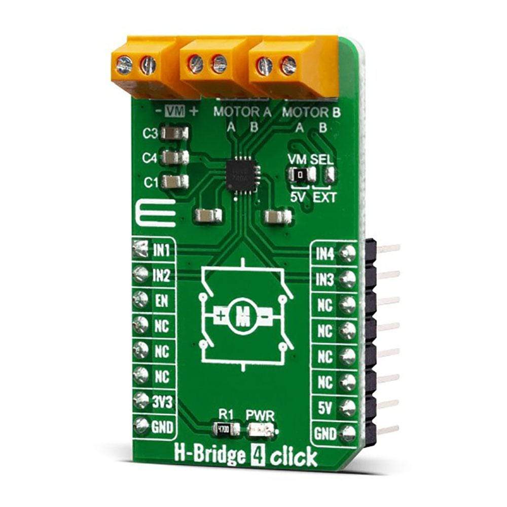
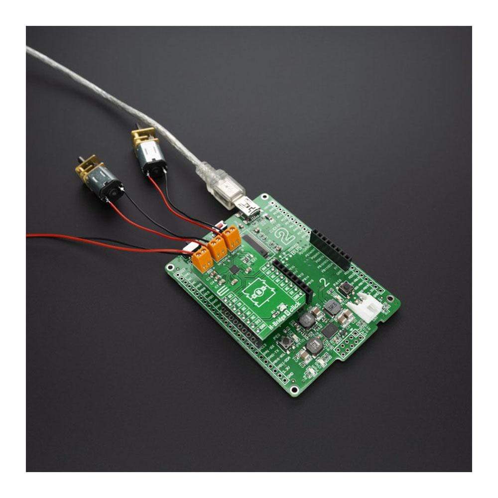
The H-Bridge 4 Click Board™ contains the AP1010AEN, which is a two-channel H-Bridge motor driver compatible with a motor operating voltage up to 18V and can drive two DC motors or one stepper motor. The protection circuit has an under-voltage lockout circuit, thermal shutdown circuit, and over-current protection circuit, and the over-current protection circuit can be disabled with the DIS OCP terminal.
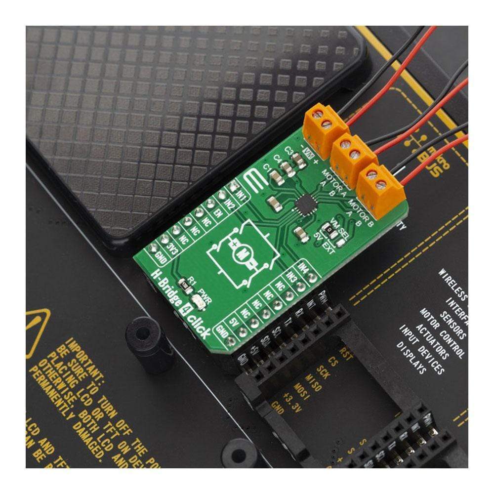
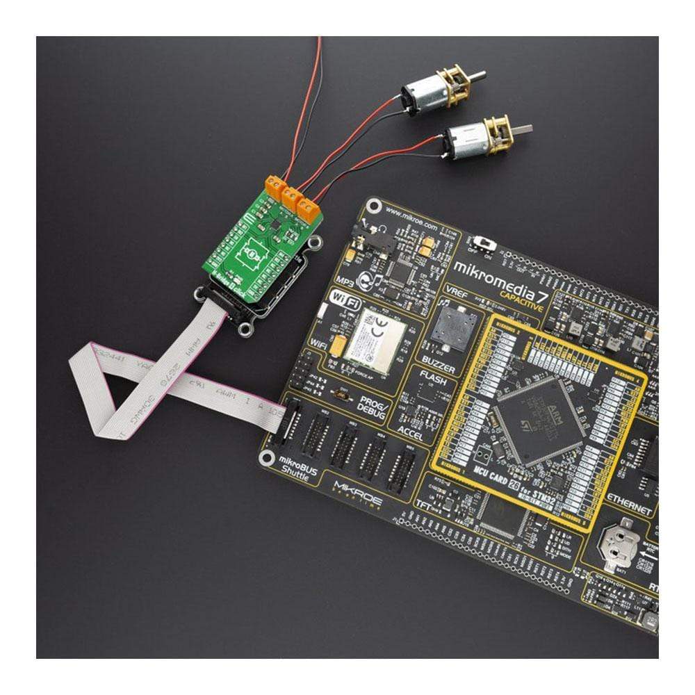
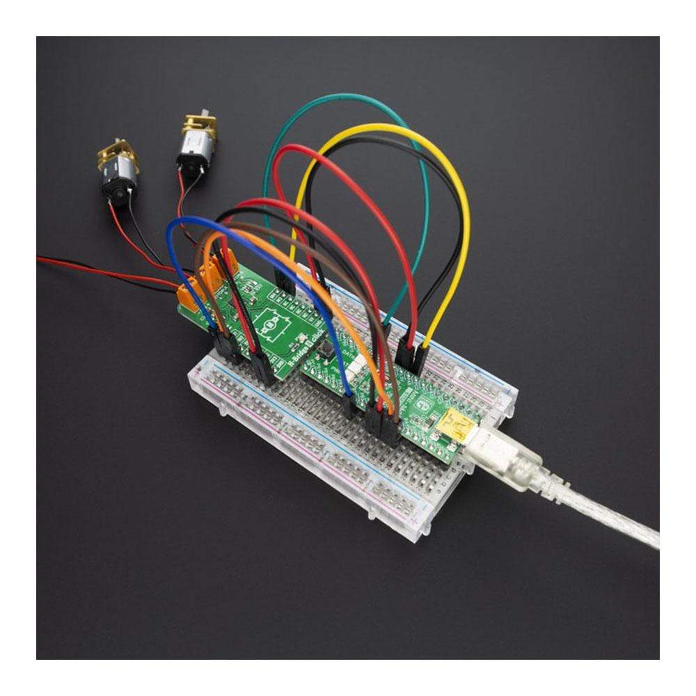
The H-Bridge 4 Click Board™ supports multiple connection options and can be used in different application setups which might include DC or Stepper motors.
Downloads
How Does The H-Bridge 4 Click Board™ Work?
The main component of the H-Bridge 4 Click Board™ is the AP1010AEN from AsahiKASEI (AKM), which is a two channel H-Bridge motor driver compatible with motor operating voltage up to. This IC is an efficient integrated H-bridge driver, with very low RDS ON output per switch. H-bridge in general, allows the current to flow in one or another direction. The output stages consist of four n-channel mosfets in H-bridge configuration. The outputs are protected against short circuits and over temperature. The bridge is controlled using the inputs IN1, IN2, IN3, and IN4, which are witer to the AN, RST, INT, and PWM pins on the mikroBUS™, respectively.
.jpg)
Its motor operating voltage range is between 6.0V~18V and control power supply is unnecessary. When it comes to its maximum output current (DC) its 0.7A @Ta=25°C and it has H-Bridge On-Resistance, which equals RON(TOP+BOT) = 1.1Ω @Ta=25°C. The Click board™ has an onboard motor voltage supply selection switch, although it is recommended to use the external power supply. The AP1010AEN also has the possibility of a parallel connection, under voltage lockout circuit and the thermal shutdown circuit. The Overcurrent protection circuit is disabled when DIS OCP terminal = "H" and the operating Temperature Range is between -30°C~85°C.
When the internal temperature of the IC reaches the specified temperature (TTSD=155°C), and the H-Bridge driver outputs Hi-Z. When the internal temperature after the detection is lowered about 30°C (TTSDHYS), the driver resumes operation. Restart Temperature = TTSD - TTSDHYS
When the current of 2.6 A or more continues to flow to the H - Bridge driver for 10 μs, all H - Bridge driver outputs are set to Hi - Z, and automatically return after 200 ms. Over current protection circuit can be used by setting the DIS OCP terminal to L level. When not using the overcurrent protection circuit, connect the DIS OCP terminal to the VDC terminal.
SPECIFICATIONS
| Type | Brushed,Stepper |
| Applications | The H-Bridge 4 Click Board™ can be used for a wide range of different applications which require two DC motors or one stepping motor. |
| On-board modules | AP1010AEN, which is a 2ch H-Bridge motor driver compatible with a motor operating voltage 18V |
| Key Features | The protection circuit has under voltage lockout circuit, thermal shutdown circuit, and overcurrent protection circuit, and overcurrent protection circuit can be disabled with the DIS OCP terminal |
| Interface | GPIO |
| Compatibility | mikroBUS |
| Click board size | M (42.9 x 25.4 mm) |
| Input Voltage | 3.3V,5V |
PINOUT DIAGRAM
This table shows how the pinout of the H-Bridge 4 Click Board™ corresponds to the pinout on the mikroBUS™ socket (the latter shown in the two middle columns).
| Notes | Pin | Pin | Notes | ||||
|---|---|---|---|---|---|---|---|
| Lead-off detection for IN- | IN1 | 1 | AN | PWM | 16 | IN4 | Lead-off detection for IN- |
| Lead-off detection for IN+ | IN2 | 2 | RST | INT | 15 | IN3 | Lead-off detection for IN+ |
| Enable | EN | 3 | CS | RX | 14 | NC | |
| NC | 4 | SCK | TX | 13 | NC | ||
| NC | 5 | MISO | SCL | 12 | NC | ||
| NC | 6 | MOSI | SDA | 11 | NC | ||
| Power Supply | 3.3V | 7 | 3.3V | 5V | 10 | 5V | Power Supply |
| Ground | GND | 8 | GND | GND | 9 | GND | Ground |
ONBOARD SETTINGS AND INDICATORS
| Label | Name | Default | Description |
|---|---|---|---|
| LD1 | PWR | - | Power LED Indicator |
| JP1 | VM SEL | - | Select motor voltage |
| General Information | |
|---|---|
Part Number (SKU) |
MIKROE-3787
|
Manufacturer |
|
| Physical and Mechanical | |
Weight |
0.019 kg
|
| Other | |
EAN |
8606018719891
|
Frequently Asked Questions
Have a Question?
Be the first to ask a question about this.