


Mikroelektronika d.o.o.
Magnetic Linear Click Board™
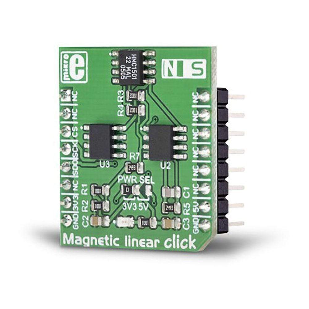
Magnetic Linear Click Board™
SKU: MIKROE-3274
Couldn't load pickup availability


Overview
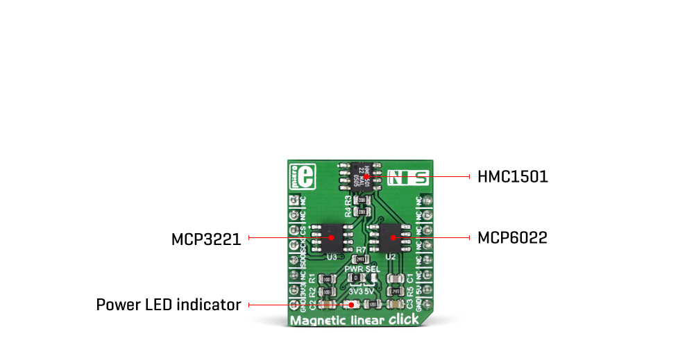
The Magnetic linear Click Board™ is a very accurate position sensing Click Board™ which utilizes the HMC1501, a magnetic field displacement sensor IC. This integrated sensor uses a single saturated-mode Wheatstone bridge which consists of four magneto-resistive elements. The precision of up to 0.07° in the angular range of ±45° can be easily achieved using the Magnetic linear Click Board™, making it far more accurate than the commonly used Hall-effect sensors.
Downloads
The HMC1501 sensor IC produces a highly linear voltage output signal in respect to the magnetic field angle, available directly from the bridge via two differential output pins. To allow simplified usage, the Magnetic Linear Click Board™ features an additional A/D converter, making it a complete solution for the rapid development of various contactless position and direction sensing applications, HMI interfaces, precision measurement applications, proximity detection applications, etc.
How Does The Magnetic Linear Click Board™ Work?
The main component of the Magnetic Linear Click Board™ is the HMC1501, a linear magnetic displacement sensor, from Honeywell. The key feature of the HMC1501 IC is the high accuracy of the magnetic field sensing. Unlike most of the magnetic sensors on the market which rely on the Hall-effect, the integrated sensors of the HMC1501 IC are produced using the Honeywell's proprietary Anisotropic Magneto-Resistive (AMR) technology, which yields an absolute magnetic angle sensing with the angular error of only 0.07° in the range of ±45°. The magneto-resistive sensing elements form a single saturated-mode Wheatstone bridge, positioned in the XZ plane (parallel with the surface of the IC). The bridge is positioned towards the edge of the IC casing, allowing which is the optimal position for linear sensing applications. The IC outputs an analog differential voltage with respect to the angle of the magnetic field.
The voltage from the selected mikroBUS™ power rail is directly applied to the internal Wheatstone bridge of the HMC1501. By construction, in the absence of the magnetic field, its outputs will be set at half the supply voltage (with the small offset of 3mV/V typically). The same applies if there is a magnetic field present, but it is positioned at 0° (zero-crossing) in respect to the bridge. In both cases all the magneto-resistive elements forming the bridge, will have identical resistances. Once the magnetic field is applied in any direction in the range of ±45°, the bridge will become unbalanced, resulting with voltage change on the outputs, which can be calculated using the following formula:
Where:
- ΔV is a differential output voltage
- VS is the power supply voltage (3.3V or 5V)
- S is the material constant (12mV/V)
- Θ is the angle of the magnetic field
The datasheet of the HMC1501 offers a more detailed explanation, along with some use cases. However, Magnetic linear click is supported by the mikroSDK library, which offers easy to use functions. All necessary calculations are encapsulated in these functions, allowing rapid application development. The included example application can be used as a reference and a starting point for a custom design.
Outputs of the Wheatstone bridge are routed to the operational amplifier, which serves as the buffer for the A/D converter. For this purpose, only a single channel of the MCP6022, a dual rail-to-rail op-amp from Microchip, is used. This op-amp is biased to half the power supply voltage and has a gain of 25. This buffered signal is then used as the input for the A/D converter.
The Magnetic Linear Click Board™ uses the MCP3201, a 12-bit A/D converter (ADC) with the SPI Interface, produced by Microchip. This ADC has a high resolution which can be used even for more demanding applications. At 0°, the ADC will output half of its full-scale (FS) value, and it will swing towards 0 if the angle of the magnetic field is positioned towards the negative direction, and 4095 if the angle of the magnetic field is positioned towards the positive direction. This ADC has a dedicated voltage reference input pin, allowing ADC conversion within the range of the input signal. The converted output value can be read via the SPI interface, routed to the mikroBUS™ SPI pins for easy interfacing with a vast number of different microcontrollers (MCUs).
The power supply voltage for the whole circuit can be selected by switching the SMD jumper, labelled as PWR SEL. It offers a choice of the power supply voltage between 3.3V and 5V, available from the mikroBUS™.
SPECIFICATIONS
| Type | Magnetic |
| Applications | The Magnetic Linear Click Board™ can be used for development of various contactless position and direction sensing applications, HMI interfaces, precision measurement applications, proximity detection applications, etc. |
| On-board modules | HMC1501, a magnetic displacement sensor, from Honeywell; MCP6022, a dual, rai-to-rail operational amplifier; MCP3201, a 12-bit A/D converter with SPI interface by Microchip |
| Key Features | A very high precision is achieved by implementing the proprietary Anisotropic magneto-resistive (AMR) technology from Honeywell, absolute sensing of the magnetic field, very compact size, differential outputs from the internal Wheatstone bridge |
| Interface | SPI |
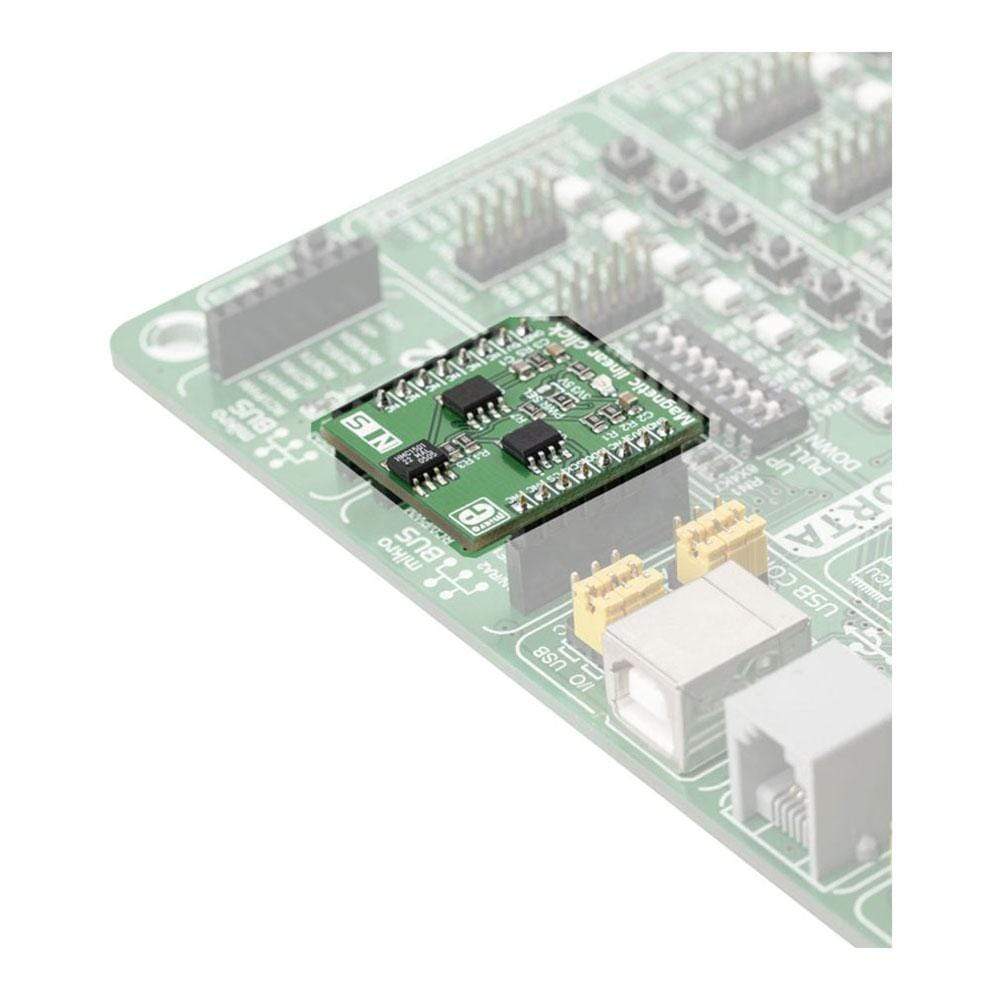
| Compatibility | mikroBUS |
| Click board size | S (28.6 x 25.4 mm) |
| Input Voltage | 3.3V or 5V |
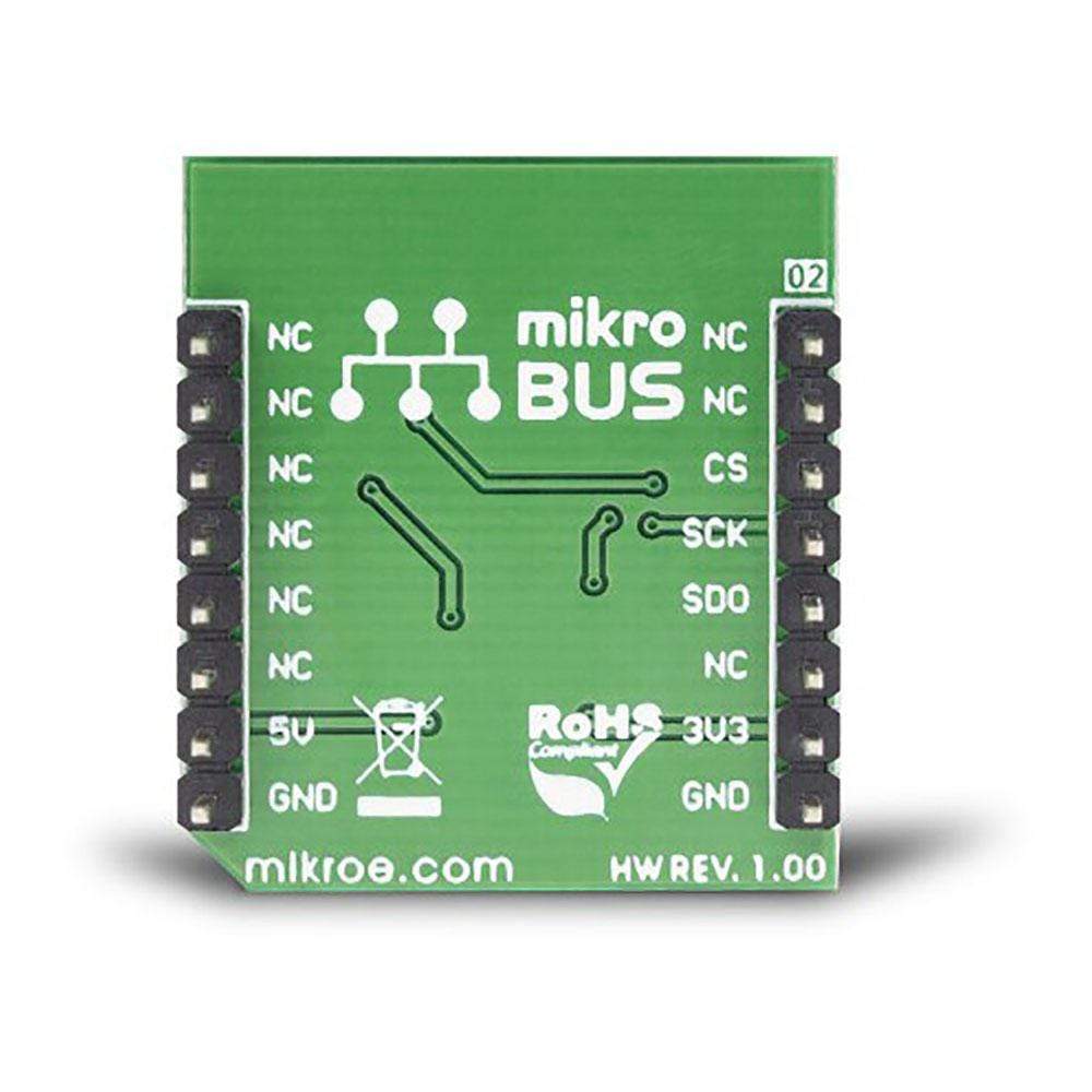
PINOUT DIAGRAM
This table shows how the pinout on the Magnetic Linear Click Board™ corresponds to the pinout on the mikroBUS™ socket (the latter shown in the two middle columns).
| Notes | Pin | Pin | Notes | ||||
|---|---|---|---|---|---|---|---|
| NC | 1 | AN | PWM | 16 | NC | ||
| NC | 2 | RST | INT | 15 | NC | ||
| SPI Chip Select | CS | 3 | CS | RX | 14 | NC | |
| SPI Clock | SCK | 4 | SCK | TX | 13 | NC | |
| SPI Data OUT | SDO | 5 | MISO | SCL | 12 | NC | |
| NC | 6 | MOSI | SDA | 11 | NC | ||
| Power supply | 3V3 | 7 | 3.3V | 5V | 10 | 5V | Power supply |
| Ground | GND | 8 | GND | GND | 9 | GND | Ground |
ONBOARD SETTINGS AND INDICATORS
| Label | Name | Default | Description |
|---|---|---|---|
| LD1 | PWR | - | Power LED indicator |
| J1 | PWR SEL | Left | Power supply voltage selection: left position 3.3V, right position 5V |
| General Information | |
|---|---|
Part Number (SKU) |
MIKROE-3274
|
Manufacturer |
|
| Physical and Mechanical | |
Weight |
0.019 kg
|
| Other | |
EAN |
8606018714025
|
Frequently Asked Questions
Have a Question?
Be the first to ask a question about this.