


Mikroelektronika d.o.o.
Driver Click Board™
Driver Click Board™
SKU: MIKROE-3109
Couldn't load pickup availability

Overview
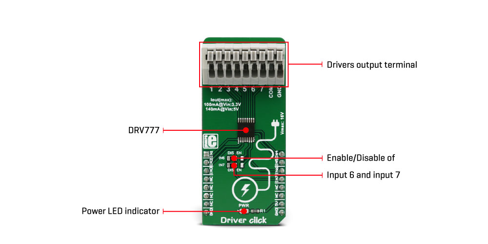
The Driver Click Board™ features an IC with seven integrated high-current sink drivers, which can be used to drive a wide range of loads via a simple parallel interface. These integrated drivers use high-efficiency MOSFETs for improved thermal performance. The DRV777 integrated motor and relay driver IC from Texas Instruments is the main active element of this Click Board™.
It is ideally suited for driving motors, relays, and similar inductive loads, as it features an internal free-wheeling diode for inductive kickback protection, on every channel. It operates with voltages up to 20 V, and by combining all the channels, it can sink up to 1A of current.
Downloads
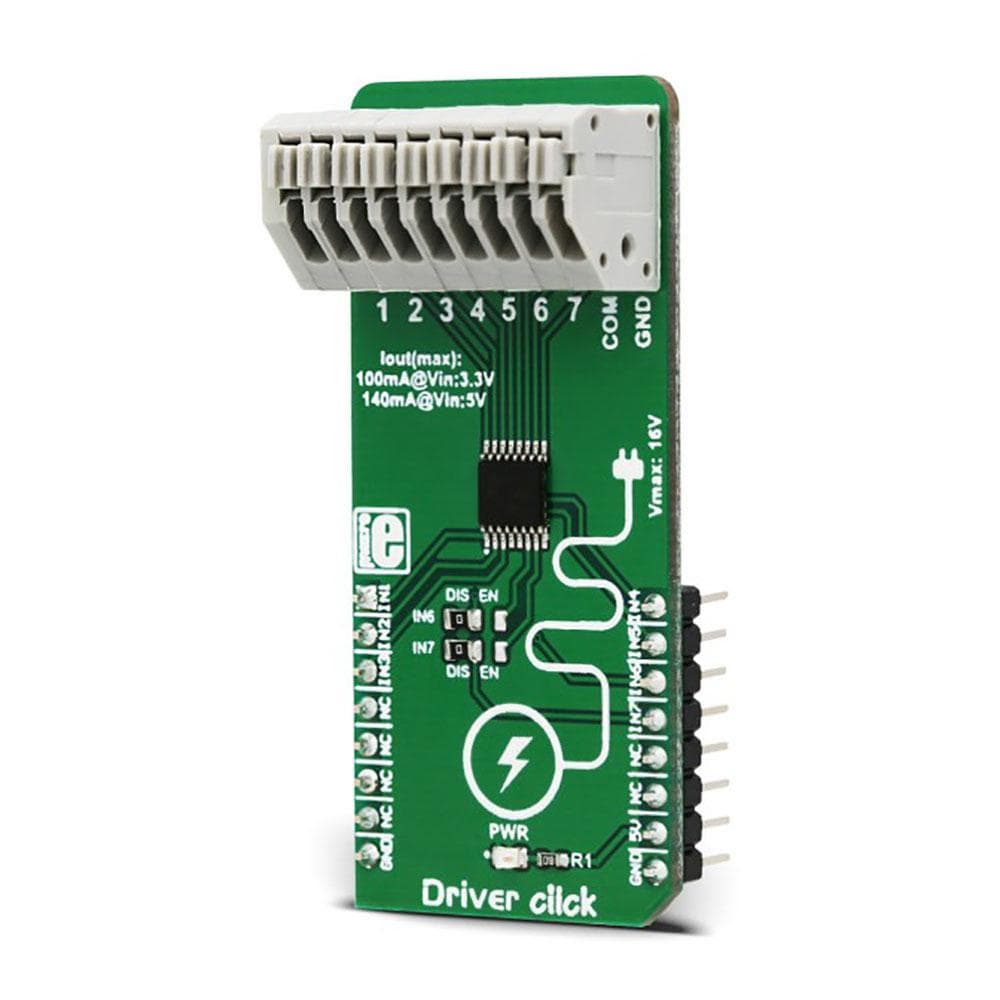
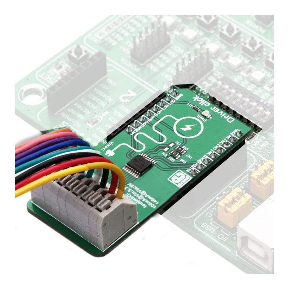
The Driver Click Board™ retains the connection flexibility of the DRV777 IC, offering a nine-pole spring terminal that can be used to implement and realize a wide range of different applications. Featuring kickback protection diodes, high impedance control inputs, input RC snubber network for improved reliability, pull-down input resistors that allow tri-stating, up to 2kV ESD protection, and more, this Click board™ is a perfect solution for developing various types of motor driving applications, regardless of whether it is a stepper motor, brushed DC motor, brushless motor, or a combination of these. A special feature of the Driver Click Board™ is the possibility to combine integrated drivers in parallel, allowing to sink up to 1A of current.
How Does The Driver Click Board™ Work?
The Driver Click Board™ uses the DRV777, an integrated motor and relay driver from Texas Instruments. This IC has seven integrated current sink drivers. Each channel has a free-wheeling diode, connected to a common pin (COM) used for an inductive kickback voltage protection. This kickback voltage is typically observed at electromotors and relays, so the existence of such a protection makes this driver a good choice for driving motors, relays, and other inductive loads, which can generate back EMF.
Each output is controlled by an input pin. Logic HIGH level on the input will result in the LOW state of the corresponding output, allowing a single driver to sink up to 140mA. The input logic voltage level can range between 1.8V and 5V, thus allowing a wide range of MCUs to be used. The input stage is filtered through an RC snubber filter, allowing the Click board™ to be used in a noisy environment. Logic LOW on the input pin will set the output driver to a HIGH logic level, allowing up to 16V (20V absolute maximum) between the pin and the ground. While in a HIGH state, the output driver will not sink current. For this reason, the input is equipped with the weak pull-down resistor, allowing inputs to be left floating or tri-stated, ensuring that the output drivers will not accidentally drive the connected load.
The output drivers are capable of sinking up to 140mA per channel. However, the DRV777 IC allows outputs to be used in parallel, combining the current that can be sink. This allows sinking up to 1A of current when all the drivers are combined. In addition, more Click board™ can be combined, allowing sinking even more current.
The Driver Click Board™ is equipped with the nine-pole spring terminal. Each output is routed to the terminal, with the addition of the COM pin and GND. This pin is a common cathode pin for all the free-wheeling diodes and a special care should be taken to connect this pin to the same voltage potential as the connected load. If not connected, a permanent damage might occur to the output drivers. GND for the load should be connected to the GND input of the nine-pole spring terminal. By using the output connector, various connections can be implemented with the same Click board™. Drivers can drive relays, motors, or a combination of these. The DRV777 datasheet offers several connecting and driving solutions. It also offers more in-depth information about the IC itself.
Although the IC uses only the 5V power rail from the mikroBUS™, the Driver Click Board™ can be freely interfaced to either 3.3V or 5V MCUs. It does not require a special jumper for the logic voltage level selection. However, it has two SMD jumpers labelled as IN6 and IN7, used to enable or disable these driver inputs. It is done so to prevent eventual interference with the UART module in some cases, as these two pins are routed to the mikroBUS™ RX and TX pins. The complete pinout is contained at the table below.
SPECIFICATIONS
| Type | Stepper |
| Applications | The Driver Click Board™ is an ideal solution for implementing various types of motor driver applications, whether driving a stepper motor, brushed DC motor, relay, or any combination of these |
| On-board modules | DRV777, an integrated motor and relay driver from Texas Instruments. |
| Key Features | Seven independent sink current drivers, with the kickback protection and ability to be combined for a greater current sinking capacity. ESD protection of 2kV that exceeds JESD 22 specs, input snubber RC network ensures reliable operation, can be controlled by a wide range of logic voltage levels. |
| Interface | GPIO |
| Compatibility | mikroBUS |
| Click board size | L (57.15 x 25.4 mm) |
| Input Voltage | 5V |
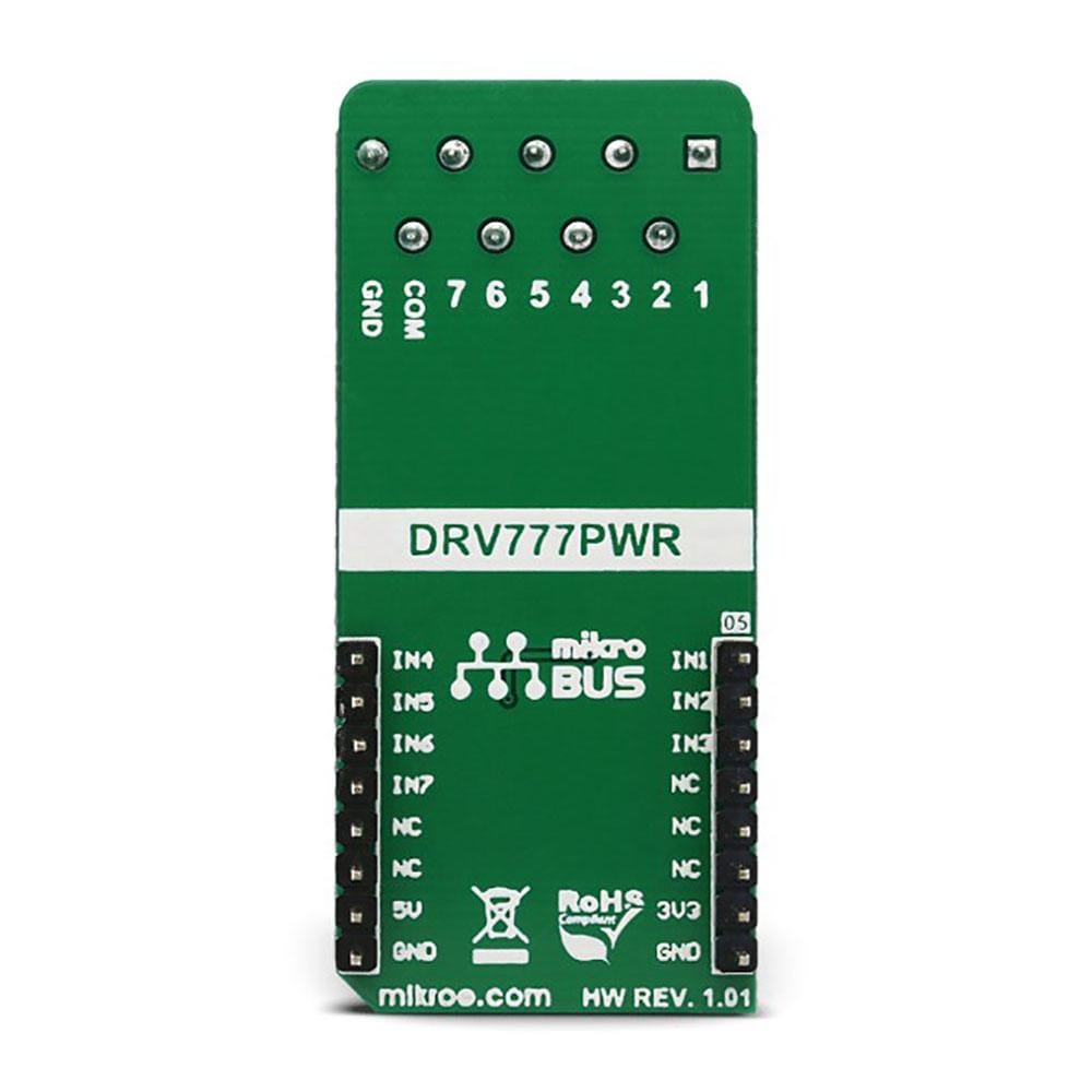
PINOUT DIAGRAM
This table shows how the pinout of the Driver Click Board™ corresponds to the pinout on the mikroBUS™ socket (the latter shown in the two middle columns).
| Notes | Pin | Pin | Notes | ||||
|---|---|---|---|---|---|---|---|
| IN1 | IN1 | 1 | AN | PWM | 16 | IN4 | IN4 |
| IN1 | IN2 | 2 | RST | INT | 15 | IN5 | IN5 |
| IN1 | IN3 | 3 | CS | RX | 14 | IN6 | IN6 |
| NC | 4 | SCK | TX | 13 | IN7 | IN7 | |
| NC | 5 | MISO | SCL | 12 | NC | ||
| NC | 6 | MOSI | SDA | 11 | NC | ||
| Power supply | 3.3V | 7 | 3.3V | 5V | 10 | 5V | Power supply |
| Ground | GND | 8 | GND | GND | 9 | GND | Ground |
ONBOARD JUMPERS AND SETTINGS
| Label | Name | Default | Description |
|---|---|---|---|
| LD1 | PWR | - | Power LED indicator |
| JP1 | IN 6 | Left | Input 6 signal routing from the mikroBUS™ TX pin: left position disable, right position enable |
| JP2 | IN 7 | Left | Input 7 signal routing from the mikroBUS™ RX pin: left position disable, right position enable |
| TB4 | 1-7, COM, GND | - | Drivers output, COM and GND connection terminal |
DRIVER CLICK ELECTRICAL SPECIFICATIONS
| Description | Min | Type | Max | Unit |
|---|---|---|---|---|
| The voltage between any output pin and GND | 0 | - | 16 | V |
| Driver sink current | 0 | - | 140 | mA |
| Input pin pull-down resistance | 210 | 300 | 390 | kΩ |
| General Information | |
|---|---|
Part Number (SKU) |
MIKROE-3109
|
Manufacturer |
|
| Physical and Mechanical | |
Weight |
0.023 kg
|
| Other | |
EAN |
8606018713349
|
Frequently Asked Questions
Have a Question?
Be the first to ask a question about this.