


Mikroelektronika d.o.o.
PAC1921 Click Board™
PAC1921 Click Board™
SKU: MIKROE-2910
Couldn't load pickup availability
Overview
The PAC1921 Click Board™ is a versatile power monitoring and measuring device intended for the high speed, low latency measurements. This device can measure current, voltage or the power of the connected load. The PAC1921 Click Board™ features an integrated average power measurement, it can output the measured properties in the form of a filtered analog voltage level by using 10-bit DAC, provides 1x to 128x current binary gain, it has an integrated second order input ADC, automatic zero offset, and all the measured values are available through the serial SMBus/I2C interface.
Downloads
The PAC1921 Click Board™ is a versatile power monitoring and measuring device intended for the high speed, low latency measurements. This device can measure current, voltage or the power of the connected load. The PAC1921 Click Board™ features an integrated average power measurement, it can output the measured properties in the form of a filtered analog voltage level by using 10bit DAC, provides 1x to 128x current binary gain, it has an integrated second order input ADC, automatic zero offset, and all the measured values are available through the serial SMBus/I2C interface.
With its very low margin of error, the PAC1921 Click Board™ is perfectly suited for measurement and monitoring of electrical properties in a wide range of different applications, such as the diagnostic equipment, power supplies, industrial and power management systems, notebook and desktop computers and similar applications where high speed, low latency measurements, and power monitoring is needed.
How Does The PAC1921 Click Board™ Work?
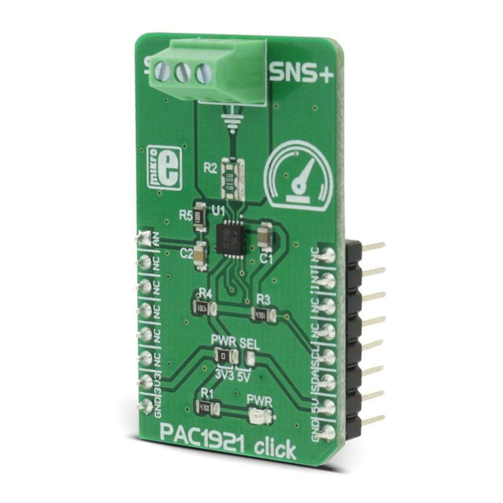
All the measurements on this PAC1921 Click Board™ are performed by the PAC1921, a high side power/current monitor from Microchip. The measurement is done by the SENSE+ and SENSE- pins, which are routed to the onboard terminals used for connecting the load. A shunt resistor of 10mΩ is also soldered between these two pins. The SENSE pins are very sensitive to the voltage and they can detect up to 100mV of across the shunt resistor. The OUT pin of the PAC1921 IC can be used to output an analog voltage, which corresponds to the selected measured electrical property - voltage, current or power. The full scale for the measurement can be set to 1V, 1.5V, 2V and 3V. The OUT pin of the IC is routed to the mikroBUS™ AN pin so that the host MCU can instantly read the measurement information without latency, common for the serial communication.
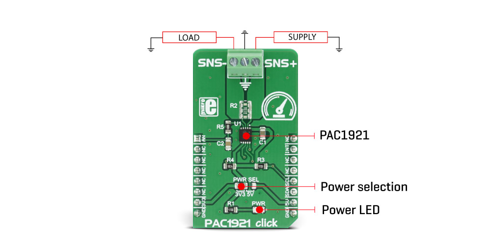
The load should be connected in series with the PAC1921 Click Board™ so that the positive end of the power supply runs through the PAC1921 click SENSE+ terminal, SENSE- terminal and finally to the positive end of the load. Negative end (GND) of the load is connected to the ground. The voltage drop across the shunt resistor is used to measure the current flow through the load and it should not exceed 6A. When the voltage drop across the shunt resistor and its resistance are known, the current can be easily calculated. The voltage across the connected power supply is measured between the SENSE+ pin and the GND. The maximum voltage level between the SENSE+ and the GND rail should not exceed 32V. During the measurement, these values are stored in the appropriate registers and are used for the power calculation.
PAC1921 IC is able to integrate the measurements so that the average value can be calculated. The integration can be done in two modes: Free-Run mode and Pin Controlled mode.
Pin Controlled integration mode can be engaged by pulling the #READ/INT pin to a HIGH level. This pin is routed to the mikroBUS™ INT pin. The measured type in this mode is limited only to power readings. While the pin is held at a HIGH logic level or before 2048 measuring samples are made, the PAC1921 IC will perform an integration of the measured values. After the integration is over - either after 2048 samples are taken, or after the #READ/INT pin is pulled to a LOW logic level for the minimum update time at any moment, the registers are updated, and the calculated value is sent to the 10bit DAC of the OUT pin. Pulling the #READ/INT pin to a LOW logic level for a minimum update time will put the device into the Read mode, stop the integration process and send the value to the 10bit DAC of the OUT pin.
While working in Free-Run integration mode, besides the power measurement, it is possible to measure current and voltage, too. The Free-Run integration time depends on the selected measuring mode, filtering, resolution, and the number of samples, which is selectable to a maximum of 2048 samples. The filtering improves the signal quality but increases the integration time for 50%. Also, when less integration time is required, 11bit ADC conversion should be used instead of the 14bit, at a cost of decreased precision. When power reading mode is selected as the measurement type, both voltage and current registers will be updated, resulting in longer integration time. While the device stays in the integration mode, the information will be latched on the DAC of the OUT pin after each integration period. When the device enters the Read mode, the integration is interrupted, and the collected data is discarded. The device is able to enter the Read mode by setting the appropriate registers, too.
While integrating the measured values, the device will place the selected measured electrical property values into the accumulator registers. At the end of the integration period, this averaged value is sent to the output 10bit DAC of the OUT pin, so that it can be read by the host MCU. It is also available in the registers, in a form of the MSB/LSB and by using conversion formulas from the PAC1921 datasheet, this value can be directly converted to the physical value of the electrical property - ampers [A], volts [V] or watts [W].
All the required setup and config registers are described in the PAC1921 datasheet, in details. However, the provided click board™ library contains functions used to easily set up the device registers and read the measurements for the selected electrical property. The provided demo application can be used as a starting point or a reference for a custom design.
The PAC1921 Click Board™ features the onboard SMD jumper, labelled as the PWR SEL, which can be used to set the operating voltage and the logic level for the SMBus/I2C communication lines so that both 3.3V and 5V capable MCUs can communicate with the device. The communication lines are already equipped with the pull-up resistors so that the device is ready to be used out of the box.
SPECIFICATIONS
| Type | Measurements |
| Applications | The PAC1921 Click Board™ is perfectly suited for measurement and monitoring of electrical properties in a wide range of different applications - diagnostic equipment, power supplies, industrial and power management systems, notebook and desktop computers, etc. |
| On-board modules | PAC1921, High-Side Power/Current Monitor with Analog Output |
| Key Features | Accurate and configurable measurement of electrical parameters, 10bit DAC routed to the analog pin output for latency free readings, smart average measurement integration available on both SMBus/I2C bus and analog output pin |
| Interface | Analog,GPIO,I2C |
| Compatibility | mikroBUS |
| Click board size | M (42.9 x 25.4 mm) |
| Input Voltage | 3.3V or 5V |
PINOUT DIAGRAM
This table shows how the pinout of the PAC1921 Click Board™ corresponds to the pinout on the mikroBUS™ socket (the latter shown in the two middle columns).
| Notes | Pin | Pin | Notes | ||||
|---|---|---|---|---|---|---|---|
| Latency-free analog OUT | AN | 1 | AN | PWM | 16 | NC | |
| NC | 2 | RST | INT | 15 | INT | Read/Integration control | |
| NC | 3 | CS | RX | 14 | NC | ||
| NC | 4 | SCK | TX | 13 | NC | ||
| NC | 5 | MISO | SCL | 12 | SCL | SMBus/I2C Clock | |
| NC | 6 | MOSI | SDA | 11 | SDA | SMBus/I2C Data | |
| Power Supply | 3V3 | 7 | 3.3V | 5V | 10 | 5V | Power Supply |
| Ground | GND | 8 | GND | GND | 9 | GND | Ground |
PAC1921 CLICK ELECTRICAL SPECIFICATIONS
| Description | Min | Typ | Max | Unit |
|---|---|---|---|---|
| SENS differential input voltage range | 0 | 100 | mV | |
| Measured current range | 0 | 6 | A | |
| Measured voltage range | 0 | 32 | V | |
| ADC input resolution | 11 | 14 | bits | |
| DAC output resolution | 10 | bits |
ONBOARD SETTINGS AND INDICATORS
| Label | Name | Default | Description |
|---|---|---|---|
| LD1 | PWR | - | Power LED indicator |
| JP1 | PWR SEL | Left | Power supply voltage level selection: left position 3.3V, right 5V |
| General Information | |
|---|---|
Part Number (SKU) |
MIKROE-2910
|
Manufacturer |
|
| Physical and Mechanical | |
Weight |
0.019 kg
|
| Other | |
EAN |
8606018712410
|
Frequently Asked Questions
Have a Question?
Be the first to ask a question about this.