


Mikroelektronika d.o.o.
IrDa 3 Click Board™
IrDa 3 Click Board™
SKU: MIKROE-2871
Couldn't load pickup availability
Overview
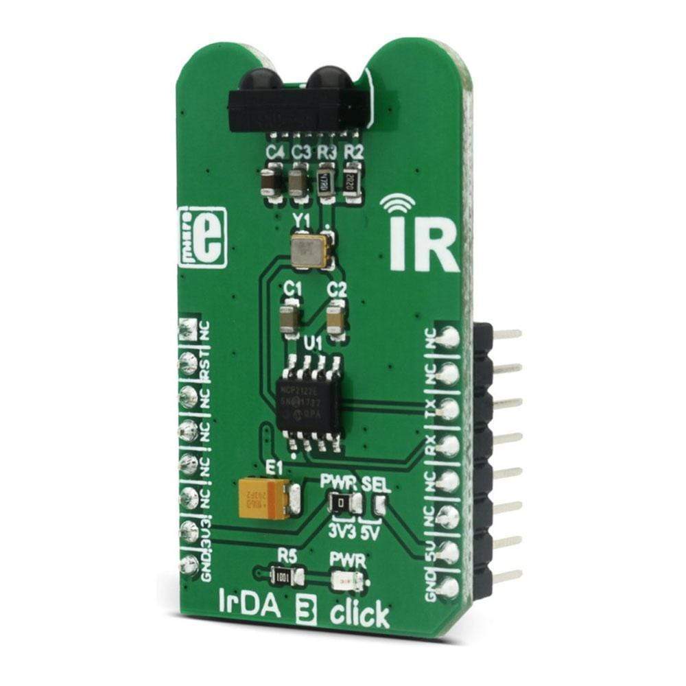
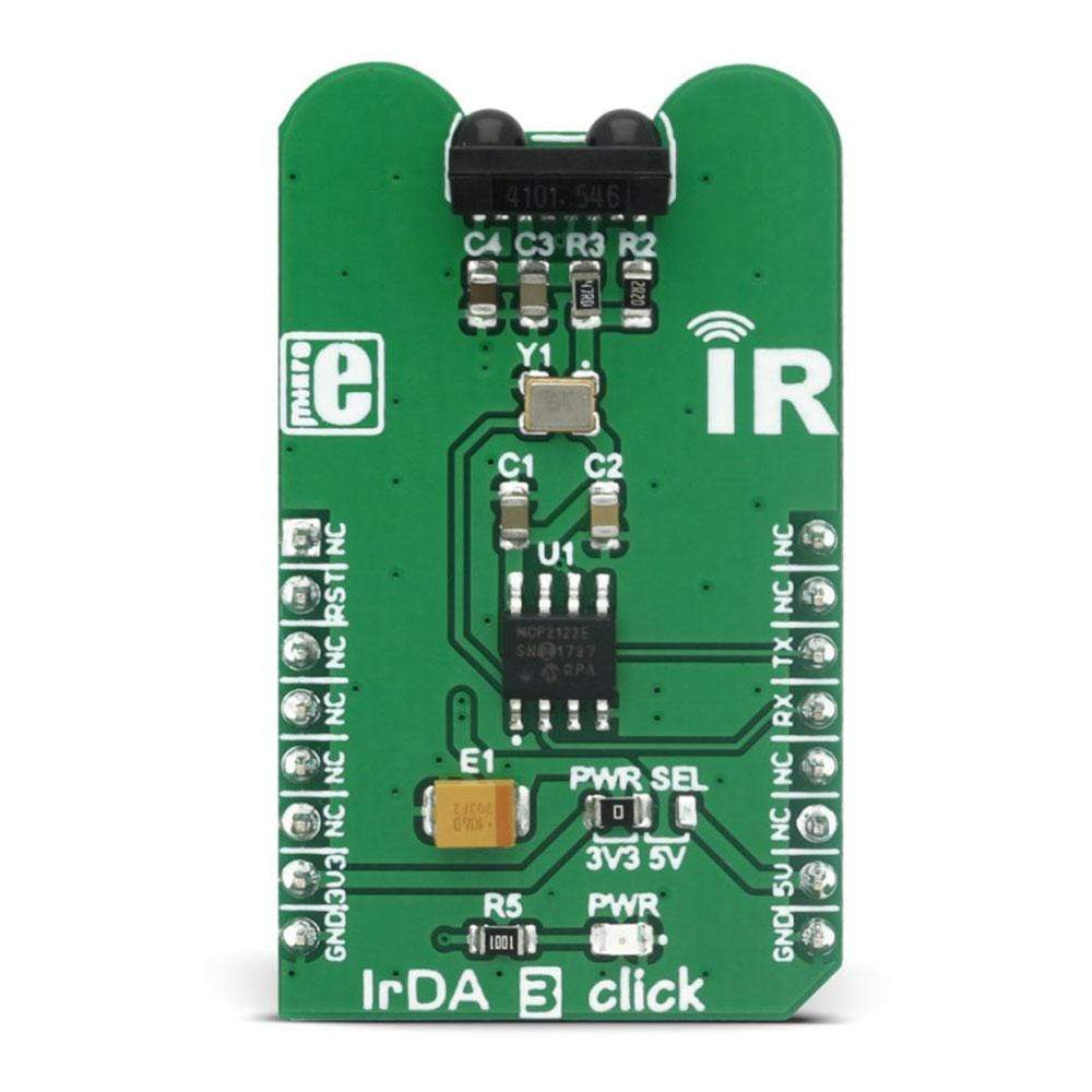
The IrDA 3 Click Board™ is an intelligent IR transceiver device that can send and receive UART commands via the IR interface. The IrDA 3 Click Board™ features both the IR transceiver and the encoder/decoder IC, used to convert the UART data and send or receive it in IrDA compatible format. IrDA 3 Click Board™ also has an onboard clock generator for the fastest possible UART performance of 115,200 bps, so it does not need an additional clock signal to be generated by the MCU.
Downloads
The IrDA 3 Click Board™ provides a direct and easy to use UART to IrDA interface. The device can be used for various applications that use the short-range remote communication, such as fax machines, photocopiers, screen projectors, TV boxes, Data loggers, GPS, various system controllers and many other IRDA standard compatible applications.
How Does The IrDA 3 Click Board™ Work?
The IrDA 3 Click Board™ is composed of two integrated devices. The first one is the TFDU4101 transceiver from Vishay, an infrared transceiver module compliant to the latest IrDA physical layer standard. It supports IrDA speeds up to 115.2 Kbps. The transceiver module is composed of the IRED (infrared emitter) and the photodiode IR receiver, which is used to both emit and receive the IR light commands. The range of this device is more than 1m and it depends on several factors. To ensure maximum possible range, the power supply is decoupled with proper capacitors, also the used oscillator is very stable and accurate, resulting with the range of about 4m.
The second IC device is the MCP2122, an infrared half duplex encoder/decoder from Microchip that takes care of the proper conversion of the UART signals to TFDU4101 acceptable IrDA standard compliant data format. The MCP2122 has its UART interface pins routed to the mikroBUS, and IrDA interface pins routed to the TFDU4101 IrDA module. The maximum communication speed for the UART interface is determined by the on-board oscillator that works at 1.8432MHz. The MCP2122 has the 16XCLK input that acts as a bit clock. The state of the bit is determined within 16 clock cycles of the 16XCLK input. This means that for every bit of the UART information, 16-bit clock cycles are needed - so the UART frequency is the bit clock frequency divided by 16, as shown by this formula: 1,843,200 / 16 = 115,200. At the same time, 115,200 is the maximum baud rate that can be used for the TFDU4101 IrDA transceiver.
The Click Board™ also has a voltage selection jumper for selecting the voltage between 3.3V and 5V. Besides the UART RX and UART TX signals routed to the mikroBUS, it also has the RESET signal routed to the RST pin of the mikroBUS. The RESET pin is used to reset the MCP2122 device. The LOW logic state on this pin will reset the device, while the HIGH state is used for a normal operation. The device can be put in a low-power state if the RST pin is held LOW. Working with this Click Board™ is easy and the demo application that comes with the Click Board™ can be used as a reference for future designs. Besides the demo application example, the library provides functions for simplified workflow with the IrDA 3 Click Board™.
Specifications
| Type | Optical |
| Applications | IrDA 3 click can be used for various applications that use the short-range remote communication, such as fax machines, photocopiers, screen projectors, TV boxes, Data loggers, GPS, various system controllers and many more. |
| On-board modules | MCP2122 - Infrared Encoder/Decoder, TFDU4101 transceiver |
| Key Features | Simple and easy to use UART to IRDA communication, the onbard encoder/decoder IC takes care of all the communication between the IR transceiver and the MCU. |
| Interface | GPIO,UART |
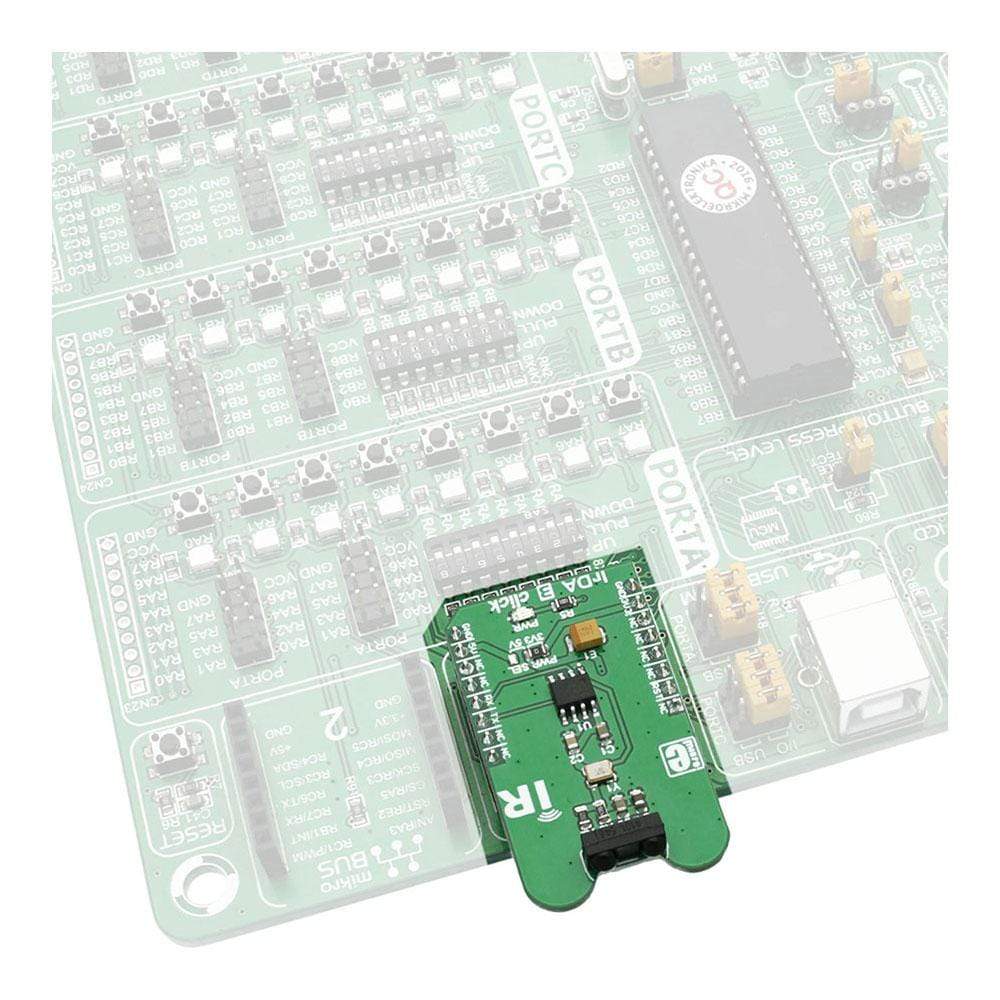
| Compatibility | mikroBUS |
| Click board size | M (42.9 x 25.4 mm) |
| Input Voltage | 3.3V or 5V |
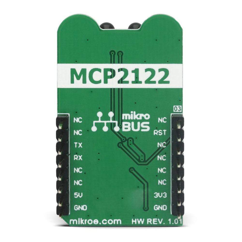
Pinout diagram
This table shows how the pinout on IrDA 3 Click Board™ corresponds to the pinout on the mikroBUS™ socket (the latter shown in the two middle columns).
| Notes | Pin | Pin | Notes | ||||
|---|---|---|---|---|---|---|---|
| NC | 1 | AN | PWM | 16 | NC | ||
| Reset | RST | 2 | RST | INT | 15 | NC | |
| NC | 3 | CS | RX | 14 | TX | UART Transmit | |
| NC | 4 | SCK | TX | 13 | RX | UART Receive | |
| NC | 5 | MISO | SCL | 12 | NC | ||
| NC | 6 | MOSI | SDA | 11 | NC | ||
| Power Supply | +3.3V | 7 | 3.3V | 5V | 10 | +5V | Power Supply |
| Ground | GND | 8 | GND | GND | 9 | GND | Ground |
IrDA 3 click electrical specifications
| Description | Min | Typ | Max | Unit |
|---|---|---|---|---|
| Input logic LOW level voltage | GND | 0.2 x VCC | V | |
| Input logic HIGH level voltage | 0.8 x VCC | VCC | V | |
| UART baud rate | 115,200 | bps |
Onboard settings and indicators
| Label | Name | Default | Description |
|---|---|---|---|
| LD1 | PWR | - | Power LED indicator |
| JP1 | PWR SEL | Left | Power supply voltage selection: left position 3V3, right position 5V |
| General Information | |
|---|---|
Part Number (SKU) |
MIKROE-2871
|
Manufacturer |
|
| Physical and Mechanical | |
Weight |
0.018 kg
|
| Other | |
EAN |
8606018712175
|
Frequently Asked Questions
Have a Question?
Be the first to ask a question about this.