

Mikroelektronika d.o.o.
LPS22HB Click Board™
LPS22HB Click Board™
SKU: MIKROE-2665
Couldn't load pickup availability


Overview
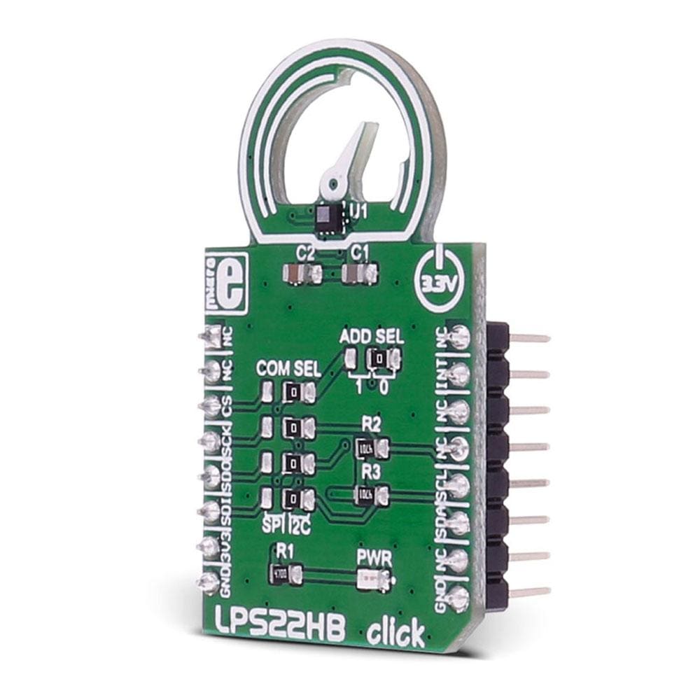
The LPS22HB Click Board™ is an easy solution for adding a digital barometer to your design. It carries the LPS22HB MEMS nano pressure sensor. The Click Board™ is designed to run on a 3.3V power supply.
The LPS22HB Click Board™ communicates with the target microcontroller over an I2C or SPI interface.
Downloads
The LPS22HB Click Board™ is an easy solution for adding a digital barometer to your design. It carries the LPS22HB MEMS nano pressure sensor. The click is designed to run on a 3.3V power supply. LPS22HB click communicates with the target microcontroller over I2C or SPI interface.
How Does The LPS22HB Click Board Work™
The LPS22HB Click Board™ carries the pressure sensor that measures 260-1260 hPa absolute pressure. Pressure values are then read out from the IC's registers, through I2C or SPI communication.
LPS22HB SENSOR FEATURES
The LPS22HB is an ultra-compact piezoresistive absolute pressure sensor which functions as a digital output barometer.
The sensing element, which detects absolute pressure, consists of a suspended membrane. When pressure is applied, the membrane deflection induces an imbalance in the Wheatstone bridge piezoresistances, whose output signal is converted by the IC interface.
The sensor has a 24-bit pressure data output and a 16-bit temperature data output.
SPECIFICATIONS
| Type | Pressure |
| Applications | Barometers for portable devices, GPS applications, Weather station equipment, etc. |
| On-board modules | LPS22HB pressure sensor |
| Key Features | 260 to 1260 hPa absolute pressure range |
| Interface | I2C,SPI,GPIO |
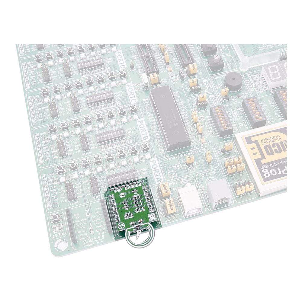
| Compatibility | mikroBUS |
| Click board size | M (42.9 x 25.4 mm) |
| Input Voltage | 3.3V |
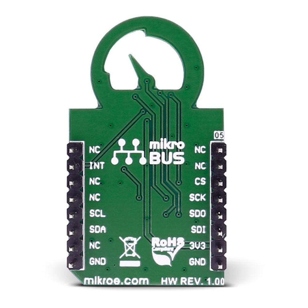
PINOUT DIAGRAM
This table shows how the pinout on LPS22HB click corresponds to the pinout on the mikroBUS™ socket (the latter shown in the two middle columns).
| Notes | Pin | Pin | Notes | ||||
|---|---|---|---|---|---|---|---|
| NC | 1 | AN | PWM | 16 | NC | ||
| NC | 2 | RST | INT | 15 | INT | Interrupt or Data Ready | |
| SPI enable | CS | 3 | CS | TX | 14 | NC | |
| SPI Clock | SCK | 4 | SCK | RX | 13 | NC | |
| SPI serial data output | SDO | 5 | MISO | SCL | 12 | SCL | I2C serial clock |
| SPI serial data input | SDI | 6 | MOSI | SDA | 11 | SDA | I2C serial data |
| Power supply | +3.3V | 7 | 3.3V | 5V | 10 | NC | |
| Ground | GND | 8 | GND | GND | 9 | GND | Ground |
MAXIMUM RATINGS
| Description | Min | Typ | Max | Unit |
|---|---|---|---|---|
| Supply VOltage (Vdd) | 1.7 | 3.6 | V | |
| IO supply voltage(Vdd_IO) | 1.7 | Vdd+0.1 | V | |
| Overpressure | 2 | MPa | ||
| Operating pressure range | 260 | 1260 | hPa | |
| Pressure sensitivity | 4096 | LSB/hPa |
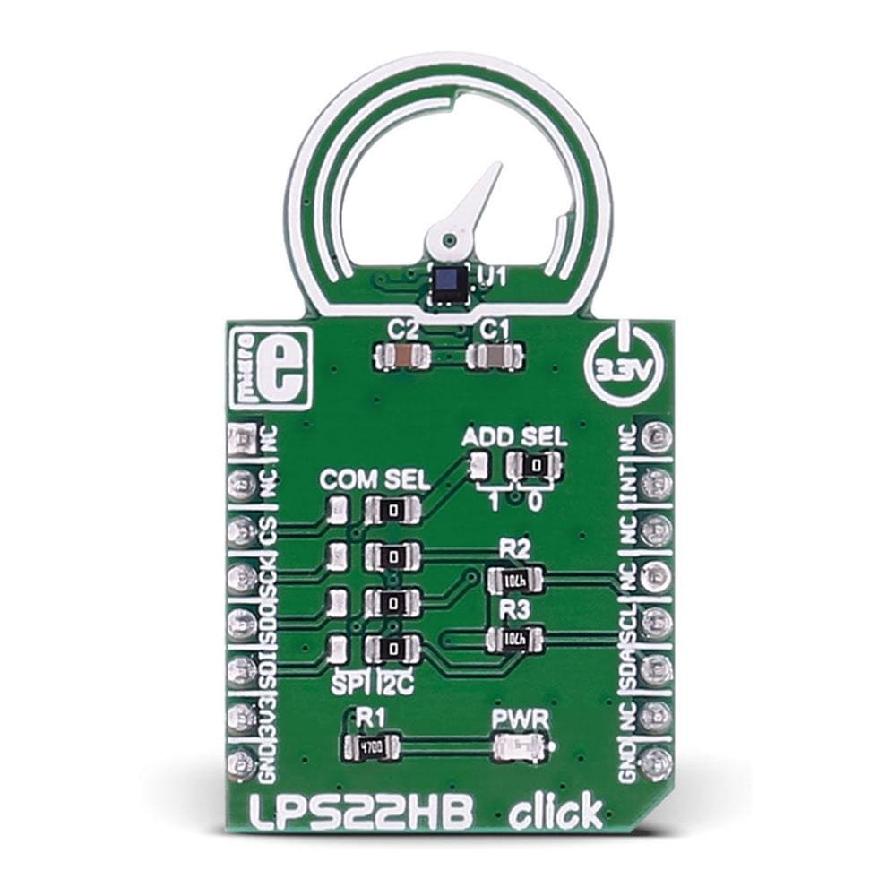
JUMPERS AND SETTINGS
| Designator | Name | Default Position | Default Option | Description |
|---|---|---|---|---|
| JP1 | COM SEL | Right | SCL(I2C) | Clock communication line Selection SCK/SCL, left position SCK, right position SCL |
| JP2 | COM SEL | Right | SDA(I2C) | Data communication line Selection SDI/SDA, left position SDI, right position SDA |
| JP3 | COM SEL | Right | ADD(I2C) | Communication Interface lines Selection SDO/ADD, left position SDO, right position ADD |
| JP4 | ADD SEL | Right | 0 | Less significant bit of the I2C slave address selection 1/0, left position 1, right position 0. |
| JP5 | COM SEL | Right | I2C | Communication interface selection CS/I2C, left position CS, right position I2C |
LEDS AND BUTTONS
| Designator | Name | Type | Description |
|---|---|---|---|
| PWR | PWR | LED | Power LED, lights green when Board is powered. |
| General Information | |
|---|---|
Part Number (SKU) |
MIKROE-2665
|
Manufacturer |
|
| Physical and Mechanical | |
Weight |
0.018 kg
|
| Other | |
EAN |
8606018710768
|
Frequently Asked Questions
Have a Question?
Be the first to ask a question about this.