


Mikroelektronika d.o.o.
CAN Isolator Click Board™
CAN Isolator Click Board™
SKU: MIKROE-2627
Couldn't load pickup availability
Overview
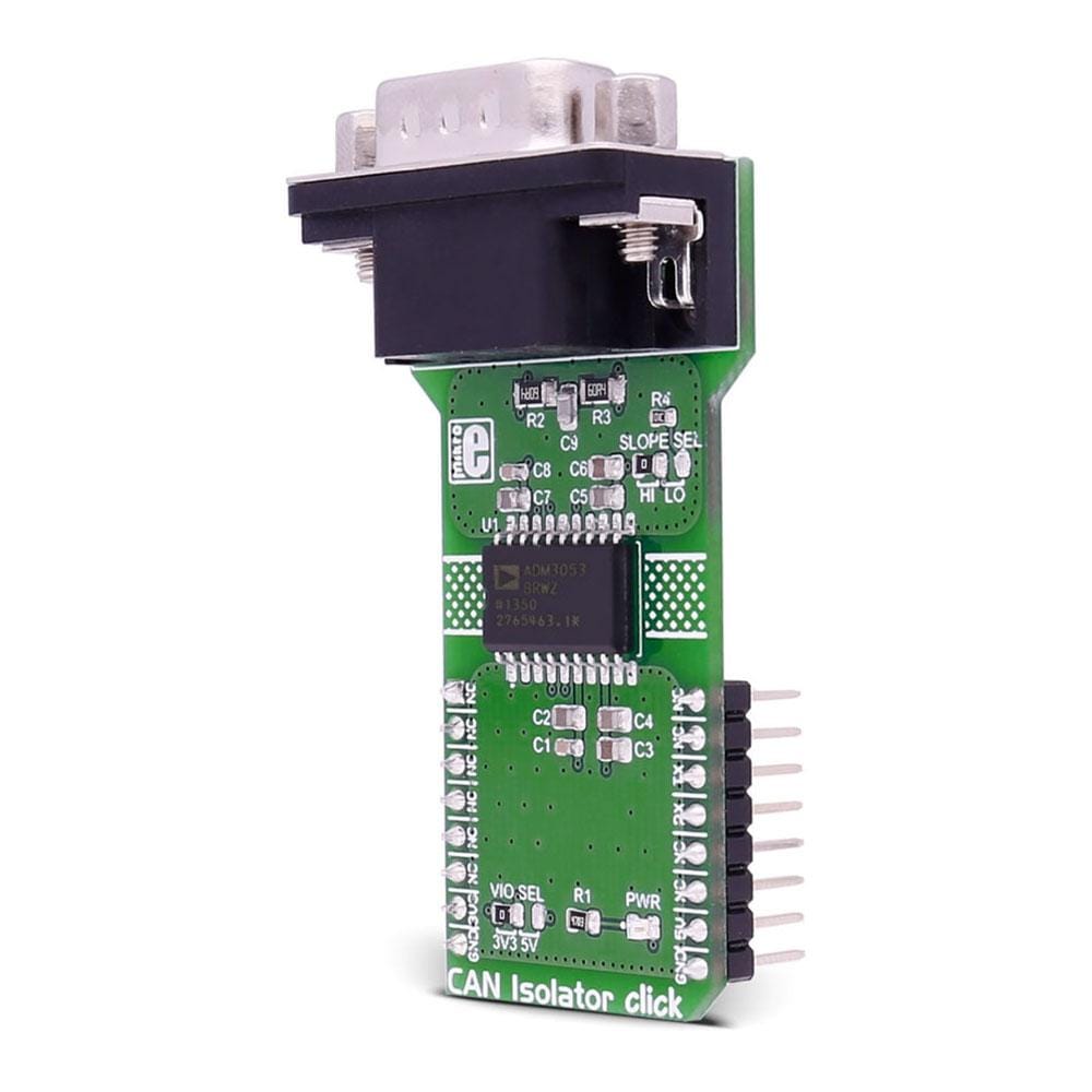
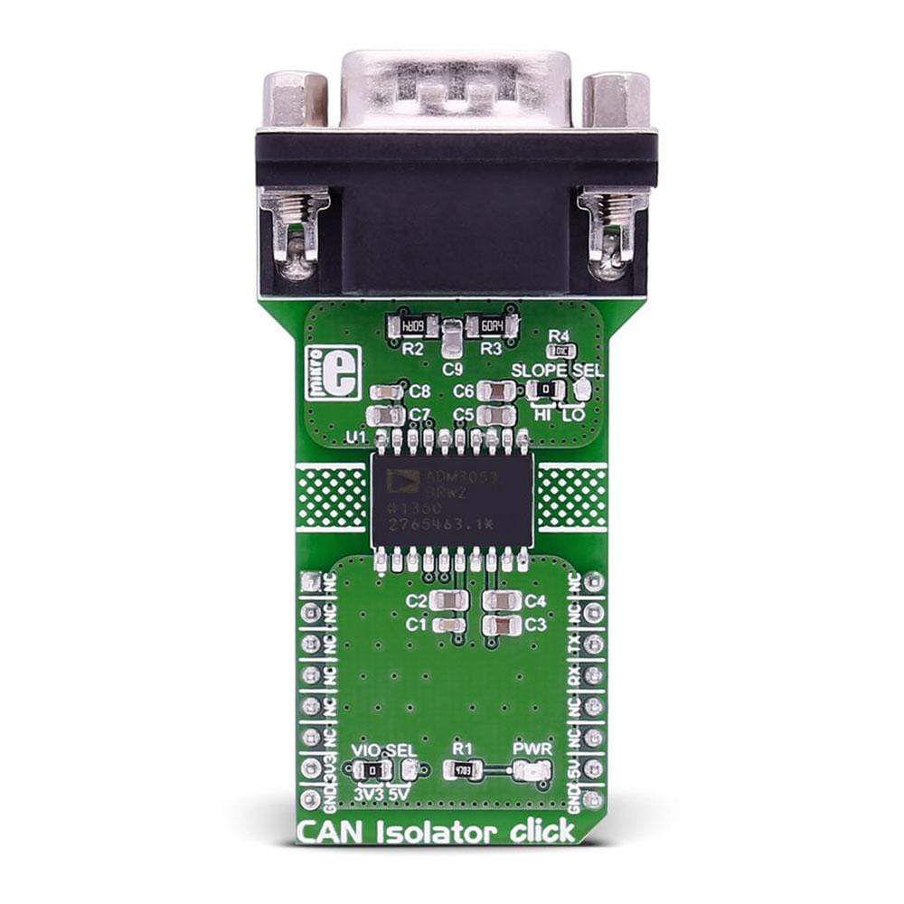
The CAN Isolator Click Board™ provides isolated CAN communication. It carries the ADM3053 signal and power isolated CAN transceiver with an integrated isolated DC-to-DC converter.
The CAN Isolator Click Board™ is designed to run on either a 3.3V or 5V power supply. CAN Isolator Click Board™ communicates with the target microcontroller over UART interface.
Downloads
The CAN Isolator Click Board™ provides isolated CAN communication. It carries the ADM3053 signal and power isolated CAN transceiver with an integrated isolated DC-to-DC converter, from Analog Devices. The click is designed to run on either 3.3V or 5V power supply. The CAN Isolator Click Board™ communicates with the target microcontroller over UART interface.
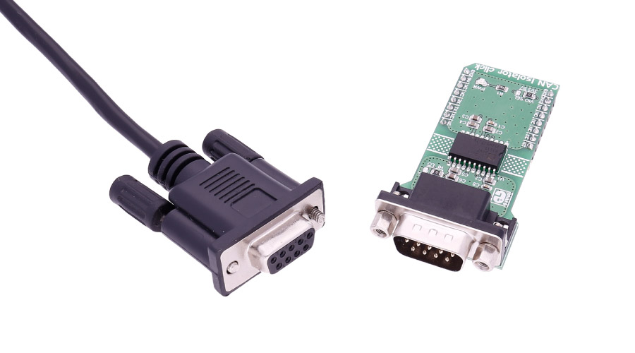
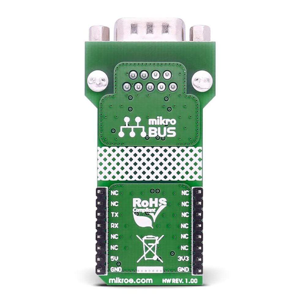
The CAN Isolator Click Board™ carries a DB 9-pin male connector.
ADM3053 FEATURES
The ADM3053 is an isolated controller area network (CAN) physical layer transceiver with an integrated isolated DC-to-DC converter.
The ADM3053 creates a fully isolated interface between the CAN protocol controller and the physical layer bus. It is capable of running at data rates of up to 1 Mbps.
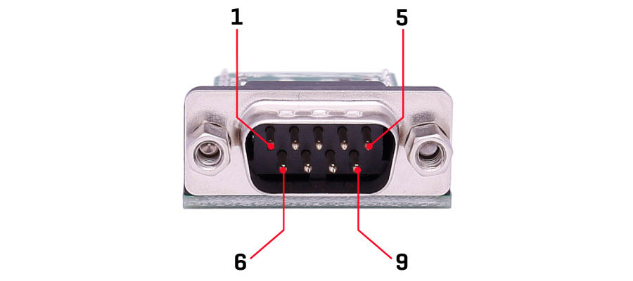
CONNECTOR FEATURES
This is a standard DB 9-pin male connector.
SPECIFICATIONS
| Type | CAN,Isolators |
| Applications | CAN data buses, Industrial field networks |
| On-board modules | ADM3053 CAN transceiver, DB 9-pin connector |
| Key Features | fully isolated interface between the CAN protocol controller and the physical layer bus. It is capable of running at data rates of up to 1 Mbps |
| Interface | UART |
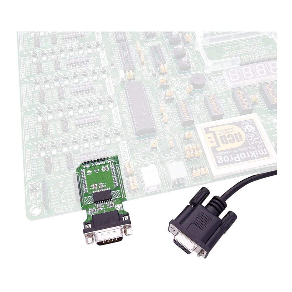
| Compatibility | mikroBUS |
| Click board size | L (57.15 x 25.4 mm) |
| Input Voltage | 3.3V or 5V |
PINOUT DIAGRAM
This table shows how the pinout of the CAN Isolator Click Board™ corresponds to the pinout on the mikroBUS™ socket (the latter shown in the two middle columns).
| Notes | Pin | Pin | Notes | ||||
|---|---|---|---|---|---|---|---|
| NC | 1 | AN | PWM | 16 | NC | ||
| NC | 2 | RST | INT | 15 | NC | ||
| NC | 3 | CS | TX | 14 | RXD | Receiver Output Data | |
| NC | 4 | SCK | RX | 13 | TXD | Driver Input Data | |
| NC | 5 | MISO | SCL | 12 | NC | ||
| NC | 6 | MOSI | SDA | 11 | NC | ||
| Power supply | +3.3V | 7 | 3.3V | 5V | 10 | +5V | Power supply |
| Ground | GND | 8 | GND | GND | 9 | GND | Ground |
JUMPERS AND SETTINGS
| Designator | Name | Default Position | Default Option | Description |
|---|---|---|---|---|
| JP1 | VIO.SEL. | Left | 3V3 | Power Supply Voltage Selection 3V3/5V, left position 3V3, right position 5V |
| JP2 | SLOPE SEL | Left | HI | Slope select, default high rate, right option the slope is limited |
| General Information | |
|---|---|
Part Number (SKU) |
MIKROE-2627
|
Manufacturer |
|
| Physical and Mechanical | |
Weight |
0.028 kg
|
| Other | |
EAN |
8606018710485
|
Frequently Asked Questions
Have a Question?
Be the first to ask a question about this.