


Mikroelektronika d.o.o.
GSM 3 Click Board™
GSM 3 Click Board™
SKU: MIKROE-1720
Couldn't load pickup availability


Overview
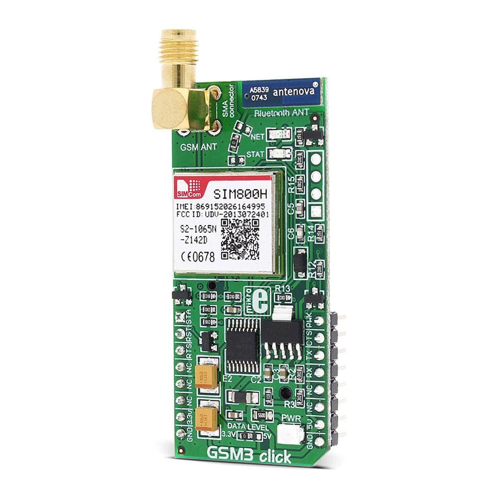
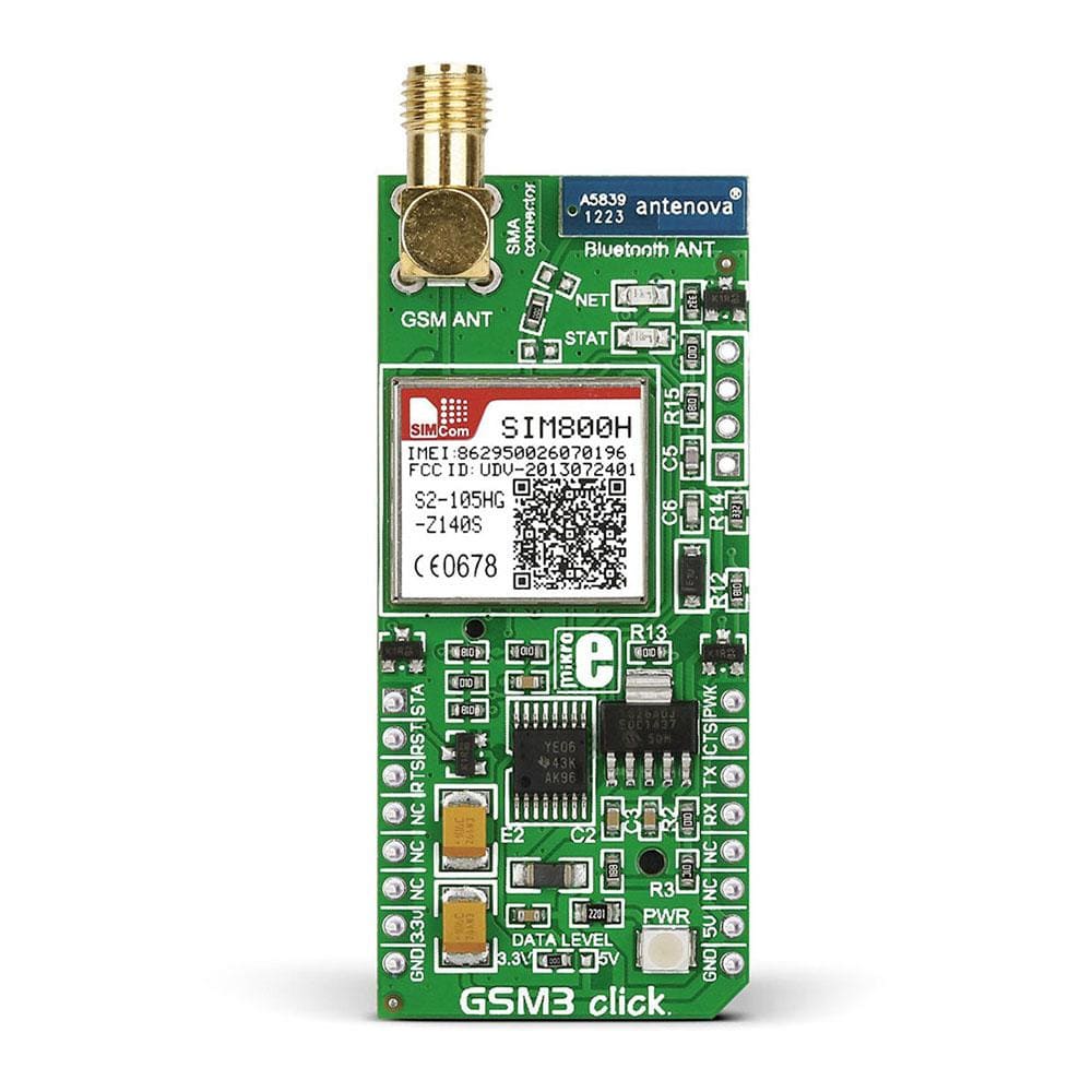
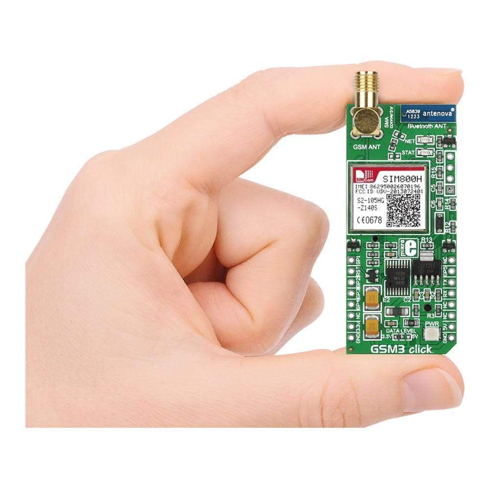
The GSM 3 Click Board™ is a complete quad-band GSM cellular network communication solution, featuring the SIM800H-BT, a quad-band 2G GSM/GPRS module. This module is GSM Phase 2/2+ compliant, featuring a full set of options for the cellular networking and communication. It has a network status indication, jamming detection, embedded internet protocols including TCP/IP, UDP, FTP, PPP, HTTP, E-mail, MMS, and more. It also features advanced voice/audio functions, including the FM radio interface. The GPRS multislot class 12 implementation allows 4 uplink and 4 downlink slots, with 5 slots open in total. Data communication speed is rated at 85.6 kbps for both uplink and downlink connection. An outstanding feature of this module is the support for the Bluetooth 3.0+ EDR protocol.
Downloads
The GSM3 Click Board™ is a complete quad-band GSM cellular network communication solution, featuring the SIM800H-BT, a quad-band 2G GSM/GPRS module. This module is GSM Phase 2/2+ compliant, featuring a full set of options for the cellular networking and communication. It has a network status indication, jamming detection, embedded internet protocols including TCP/IP, UDP, FTP, PPP, HTTP, E-mail, MMS, and more. It also features advanced voice/audio functions, including the FM radio interface. The GPRS multislot class 12 implementation allows 4 uplink and 4 downlink slots, with 5 slots open in total. Data communication speed is rated at 85.6 kbps for both uplink and downlink connection. An outstanding feature of this module is the support for the Bluetooth 3.0+ EDR protocol.
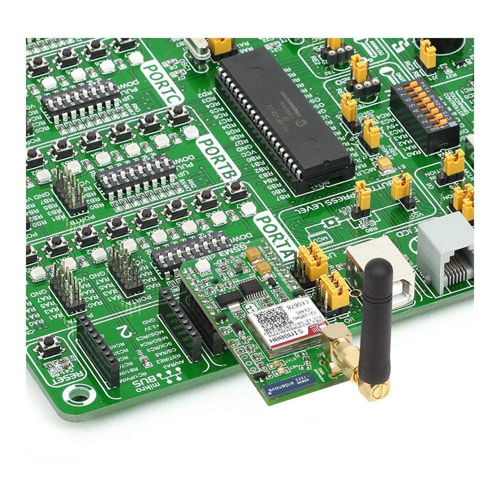
The GSM3 Click Board™ supports quad-band GSM/GPRS, allowing it to be used worldwide. A powerful set of functions, packed in the compact size module, driven by simple AT command interface, make this click board™ a complete solution for a wide range of M2M applications, including mobile Internet terminals, automatic meter reading (AMR), remote monitoring automation and control (RMAC), surveillance and security, road pricing, asset tracking, wireless points of service (POS) and similar applications, which rely on a cellular network connection.
How Does The GSM3 Click Board™ Work?
The GSM3 Click Board™ is equipped with the SIM800H-BT, a compact, quad-band 2G GSM/GPRS module, from SIMCom. It covers frequencies of 850/900 MHz (2W of TX power) and frequencies of 1800/1900 MHz (1W of TX power). It is GPRS multislot class 12 compliant device, featuring 4 download slots / 4 upload slots, supporting 5 slots in total. This module is the main component of the click board and it consists of a number of internal blocks or sections, such as antenna switching section, RF transceiver section (BT, FM, and GSM), memory, power management, analog section (audio, ADC), and most importantly - the cellular baseband processor. The module interface consists of several lines used to report the device and the network status, SIM card interface lines, UART interface lines, and device control lines. These lines are routed to the respective elements of the click board.
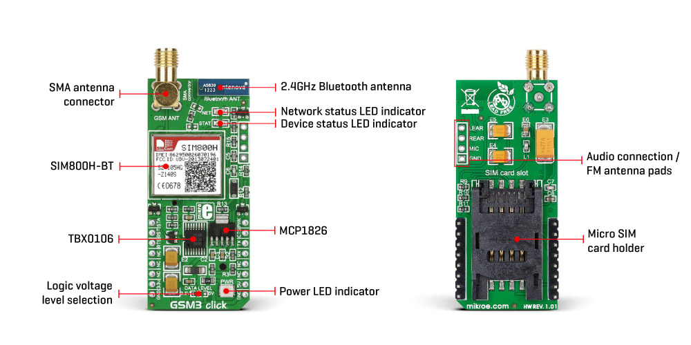
The SIM800H-BT module has to be powered by a clean and stable power supply. The voltage needed for the module to work properly is about 4V and it is derived from the 5V mikroBUS™ rail, through the MCP1826, a 1A low drop output (LDO) regulator from Microchip. Although the SIM800H is a low power device, the cellular network modules in general, are notorious for their high power consumption, so the 1A LDO had to be used.
Digital sections of the SIM800H-BT are internally supplied by 2.8V, so it is necessary to condition the communication bus lines which connect the host MCU with the module. SIM800H-BT outputs 2.8 V from its internal LDO, providing the needed reference voltage for one side of the TXB0106, a 6bit bidirectional level shifting and voltage translator with automatic direction sensing, from Texas Instruments. The reference voltage for the other side of the level shifter is taken from the onboard SMD jumper, labelled as I/O Level This jumper is used to select between 3.3V and 5V from the mikroBUS™, depending on the used MCU type and its logic voltage level requirements.
UART interface supports standard baud rates ranging from 1200 bps up to 115.2 kbps. The automatic baud rate detection is supported for baud rates up to 57.6 kbps. The automatic baud rate detection is set by default. Some responses are not transmitted by the device in the case when the automatic baud rate detection is turned on. The baud rate settings are stored into the internal non-volatile memory, so once stored these settings will be retained between power cycles.
The UART bus of the SIM800H-BT module is connected to one side of the level shifter, while the other side (shifted) is connected to the respective mikroBUS™ UART pins (TX and RX). However, the SIM800H-BT module is designed as the traditional DCE device (Data Communication Equipment) offering the full UART pin count, including the hardware flow control pins (CTS, RTS). These pins are routed to the mikroBUS™ CS (RTS) and the INT pin (CTS) and are used when the hardware flow control is enabled.
A red LED labelled as NET is used to indicate the network status. The network status is indicated by the NET LED, using the following pattern:
- Permanently OFF: the device is unpowered
- Cyclically ON for 64ms, OFF for 800ms: network search / not registered
- Cyclically ON for 64ms, OFF for 3s: registered on the network
- Cyclically ON for 64ms, OFF for 300ms: communication is established
A yellow LED labelled as STAT is used to indicate the device status. When it is lit, the device is operational. It also signalizes that the internal module initialization is finished and that the module is ready to work. To provide enough power for the LEDs, both of them are driven via the NPN BJ transistor. The STAT pin of the module is also routed to the AN pin of the mikroBUS™, allowing monitoring of the status by the host MCU.
The PWRKEY pin is routed to the mikroBUS™ PWM pin, and it is used to manually power up/down the Click board™. Asserting this pin to a LOW logic level for at least 1s will toggle the power state of the SIM800H module. To properly detach from the network and store the working parameters in its non-volatile memory, the module should be safely powered off, either by using the PWM (PWRKEY) pin or by issuing the AT+CPOWD=1 command. Abrupt termination of the power supply might lead to a loss of the current parameter settings and improper detach from the network.
Besides the PWRKEY pin, this module also has the RESET pin, used in the case when the AT+CPOWD=1 or PWRKEY does not work. Pulling this pin to a LOW logic level will reset the device. This pin is routed to the mikroBUS™ RST pin and it is internally pulled to a HIGH logic level.
One of the stand-out features of this Click board™ is the support for the Bluetooth 3.0+ EDR protocol. The GSM3 Click Board™ is equipped with the 2.4GHz RUFA SMD antenna, from antenova®. This antenna allows BT 3.0 communication with this device.
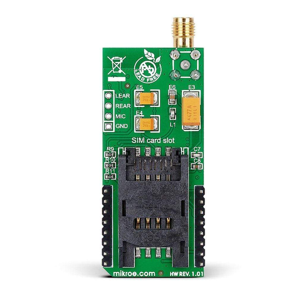
The SIM800H-BT module offers extensive audio features, including half rate, full rate, enhanced full rate and adaptive multi-rate voice codecs, superior echo cancellation, configurable with the AT commands. The audio DSP section is integrated inside the module and it requires only a few external components. The headset can be connected via the connection pad on the side of the Click board™. The pad also offers an FM antenna connection, allowing listening to the FM radio transmissions. For this purpose, a headset with the integrated FM antenna inside of the cable can be used. Functions of the FM radio receiver can be adjusted via the AT commands. The incoming call interrupts the signal from the FM receiver, and it is redirected to the headset, instead.
The Micro SIM card holder on the back of the click board™ is used to install a micro SIM card. This device cannot be used without the valid SIM card, which allows connection to the cellular network. Both 1.8V and 3V SIM card types are supported, with fast 64kbps SIM card communication speed (GSM Phase 2+).
SPECIFICATIONS
| Type | 2G GPRS,GSM/LTE |
| Applications | The GSM3 Click Board™ is a robust and reliable solution for communicating with your devices. Turn appliances on/off, exchange SMS messages for status updates and so on |
| On-board modules | SIM800H-BT |
| Key Features | 2.4 GHz Bluetooth antenna, GSM antenna connector. SIM card socket integrated at the bottom side of the board |
| Interface | GPIO,UART |
| Compatibility | mikroBUS |
| Click board size | L (57.15 x 25.4 mm) |
| Input Voltage | 3.3V or 5V |
PINOUT DIAGRAM
This table shows how the pinout on GSM3 click corresponds to the pinout on the mikroBUS™ socket (the latter shown in the two middle columns).
| Notes | Pin | Pin | Notes | ||||
|---|---|---|---|---|---|---|---|
| Device status | STA | 1 | AN | PWM | 16 | PWK | Power toggle |
| Reset | RST | 2 | RST | INT | 15 | CTS | CTS (Clear To Send) |
| RTS (Ready To Send) | RTS | 3 | CS | RX | 14 | TXD | UART TX (Transmit) |
| NC | 4 | SCK | TX | 13 | RXD | UART RX (Receive) | |
| NC | 5 | MISO | SCL | 12 | NC | ||
| NC | 6 | MOSI | SDA | 11 | NC | ||
| Power Supply | +3V3 | 7 | 3.3V | 5V | 10 | +5V | Power Supply |
| Ground | GND | 8 | GND | GND | 9 | GND | Ground |
ONBOARD SETTINGS AND INDICATORS
| Label | Name | Default | Description |
|---|---|---|---|
| JP1 | - | Left | Power Supply Voltage Selection: Left position 3V3, right position 5V |
| LD1 | PWR | - | PWR indication LED |
| NET | LD2 | - | Network status LED indicator |
| STAT | LD3 | - | Device status LED indicator |
ADDITIONAL PINS
| Name | I/O | Description |
|---|---|---|
| LEAR | O | Left earphone output |
| REAR | O | Left earphone output |
| MIC | I | Mic input |
| GND | - | Headset ground/FM antenna |
| General Information | |
|---|---|
Part Number (SKU) |
MIKROE-1720
|
Manufacturer |
|
| Physical and Mechanical | |
Weight |
0.035 kg
|
| Other | |
EAN |
8606015077468
|
Frequently Asked Questions
Have a Question?
Be the first to ask a question about this.