


Mikroelektronika d.o.o.
LED Driver 10 Click Board™
LED Driver 10 Click Board™
SKU: MIKROE-4787
Couldn't load pickup availability


Overview
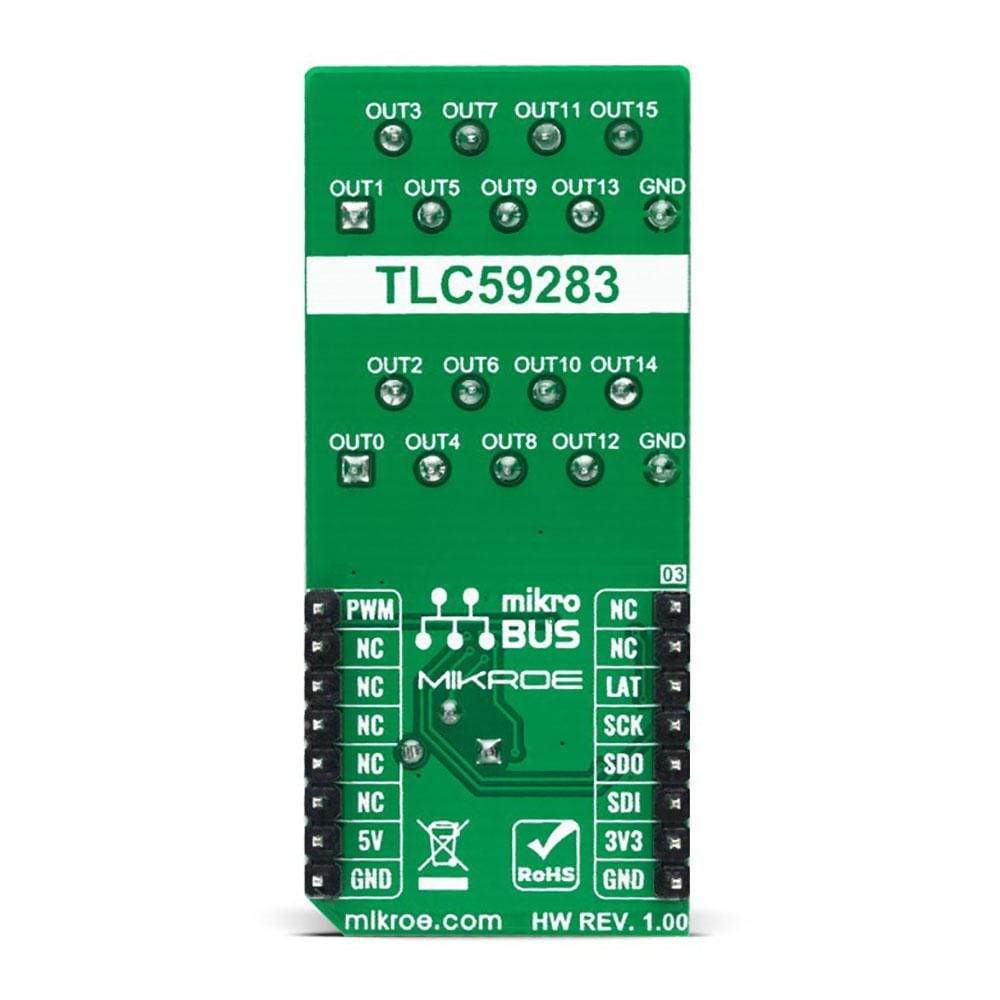
The LED Driver 10 Click Board™ is a compact add-on board that simplifies the control of multiple LEDs. This board features the TLC59283, a 16-channel, constant-current sink light-emitting diode (LED) driver with pre-charge FET from Texas Instruments. Each LED channel can be individually controlled with a simple SPI serial communication protocol compatible with both 3.3V or 5V logic levels. Each constant-current output has a pre-charge field-effect transistor that can reduce ghosting on the multiplexing drive LED display. It has additional features such as switching off all outputs via just one mikroBUS™ pin and setting the constant-current values on all 16 channels via one onboard potentiometer.
This LED Driver 10 Click Board™ is suitable for colour mixing and backlight application for amusement products, LED status signalization, home automation projects, and many more.
Downloads
How Does The LED Driver 10 Click Board™ Work?
The LED Driver 10 Click Board™ as its foundation uses the TLC59283, an SPI bus controlled, 16-channel, constant-current sink light-emitting diode (LED) driver with pre-charge FET from Texas Instruments. It operates within a VCC supply voltage range where its outputs are 10V tolerant. Each LED output, 16 LED drivers presented on two nine position spring terminals, with a maximum output current of +50mA per channel, is programmable at OFF and ON state with a programmable individual LED brightness.
The internal pre-charge FET prevents the ghosting of multiplexed LED modules. One cause of this phenomenon is the parasitic capacitance charging current of the constant-current outputs and PCB wiring connected to LED pins of the TLC59283 through the external LED.
The TLC59283 communicates with MCU using the standard SPI serial interface with a maximum frequency of 35MHz. It has a 16-bit shift register and an output ON/OFF data latch. The shift register and data latch are 16 bits long and used to turn the constant-current outputs ON/OFF. When the serial data buffer is loaded, a LAT pin of the mikroBUS™ socket rising edge transfers the data to the LED outputs. When the TLC59283 is initially powered on, the data in the 16-bit shift register and output ON/OFF data latch are not set to default values. Therefore, the output ON/OFF data must be written to the data latch before turning ON the LED output.
PWM pin of the mikroBUS™ socket should be set to a high logic state when powered on because the constant-current may be turned on due to random data in the output ON/OFF data latch. When the PWM pin is in a low logic state, the corresponding LED output is turned ON if data in the ON/OFF control data-latch are '1' and remains off if the data are '0'. When the PWM pin is high, all LED outputs are forced OFF.
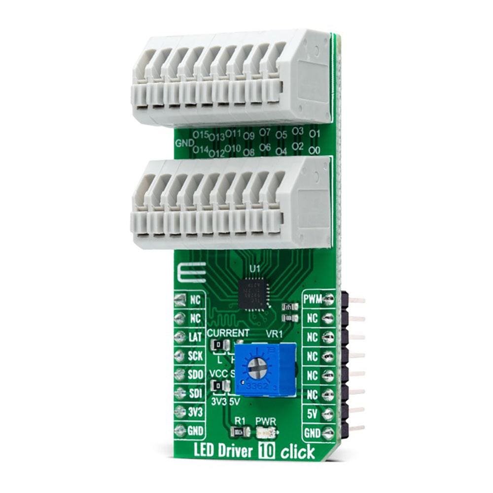
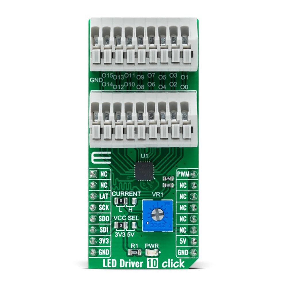
The LED Driver 10 Click Board™ also possesses the adjustable potentiometer labeled as VR1 that adjusts the constant-current value of all 16 channels. The constant-current value of all 16 channels is set by a single external resistor placed between the IREF pin, the constant-current value setting pin of the TLC59283, and the ground. Selection can be performed by onboard SMD jumper labeled as CURRENT to an appropriate position marked as L and H.
The LED Driver 10 Click Board™ can operate with both 3.3V and 5V logic voltage levels selected via the VCC SEL jumper. This way, it is allowed for both 3.3V and 5V capable MCUs to use the SPI communication lines properly. However, the Click board™ comes equipped with a library containing easy-to-use functions and an example code that can be used, as a reference, for further development.
Specifications
| Type | LED Drivers |
| Applications | Can be used for color mixing and backlight application for amusement products, LED status signalization, home automation projects, and many more |
| On-board modules | TLC59283 - SPI bus controlled, 16-channel, constant-current sink light-emitting diode (LED) driver with pre-charge FET from Texas Instruments |
| Key Features | Low power consumption, 16 channels, ON/OFF LED channels control, pre-charge FET for ghosting reduction, switching delay for noise reduction, channel-current setting, and more |
| Interface | SPI |
| Compatibility | mikroBUS |
| Click board size | L (57.15 x 25.4 mm) |
| Input Voltage | 3.3V or 5V |
Pinout diagram
This table shows how the pinout on the LED Driver 10 Click Board™ corresponds to the pinout on the mikroBUS™ socket (the latter shown in the two middle columns).
| Notes | Pin | Pin | Notes | ||||
|---|---|---|---|---|---|---|---|
| NC | 1 | AN | PWM | 16 | PWM | ON/OFF LED Channel Control | |
| NC | 2 | RST | INT | 15 | NC | ||
| SPI Chip Select | LAT | 3 | CS | RX | 14 | NC | |
| SPI Clock | SCK | 4 | SCK | TX | 13 | NC | |
| SPI Data OUT | SDO | 5 | MISO | SCL | 12 | NC | |
| SPI Data IN | SDI | 6 | MOSI | SDA | 11 | NC | |
| Power Supply | 3.3V | 7 | 3.3V | 5V | 10 | 5V | Power Supply |
| Ground | GND | 8 | GND | GND | 9 | GND | Ground |
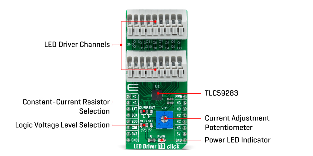
Onboard settings and indicators
| Label | Name | Default | Description |
|---|---|---|---|
| LD1 | PWR | - | Power LED Indicator |
| JP1 | VCC SEL | Left | Logic Level Voltage Selection 3V3/5V: Left position 3V3, Right position 5V |
| JP2 | CURRENT | Left | Constant-Current Resistor Selection L/H: Left position L, Right position H |
| VR1 | VR1 | - | Current Adjustment Potentiometer |
LED Driver 10 Click electrical specifications
| Description | Min | Typ | Max | Unit |
|---|---|---|---|---|
| Supply Voltage | 3.3 | - | 5 | V |
| Maximum LED Channel Output Voltage | - | - | 10 | V |
| Maximum LED Channel Output Current | - | - | 45 | mA |
| Operating Temperature Range | -40 | +25 | +85 | °C |
| General Information | |
|---|---|
Part Number (SKU) |
MIKROE-4787
|
Manufacturer |
|
| Physical and Mechanical | |
Weight |
0.02 kg
|
| Other | |
EAN |
8606027383403
|
Frequently Asked Questions
Have a Question?
Be the first to ask a question about this.