


Mikroelektronika d.o.o.
Heart Rate 9 Click Board™
Heart Rate 9 Click Board™
SKU: MIKROE-3822
Couldn't load pickup availability


Overview
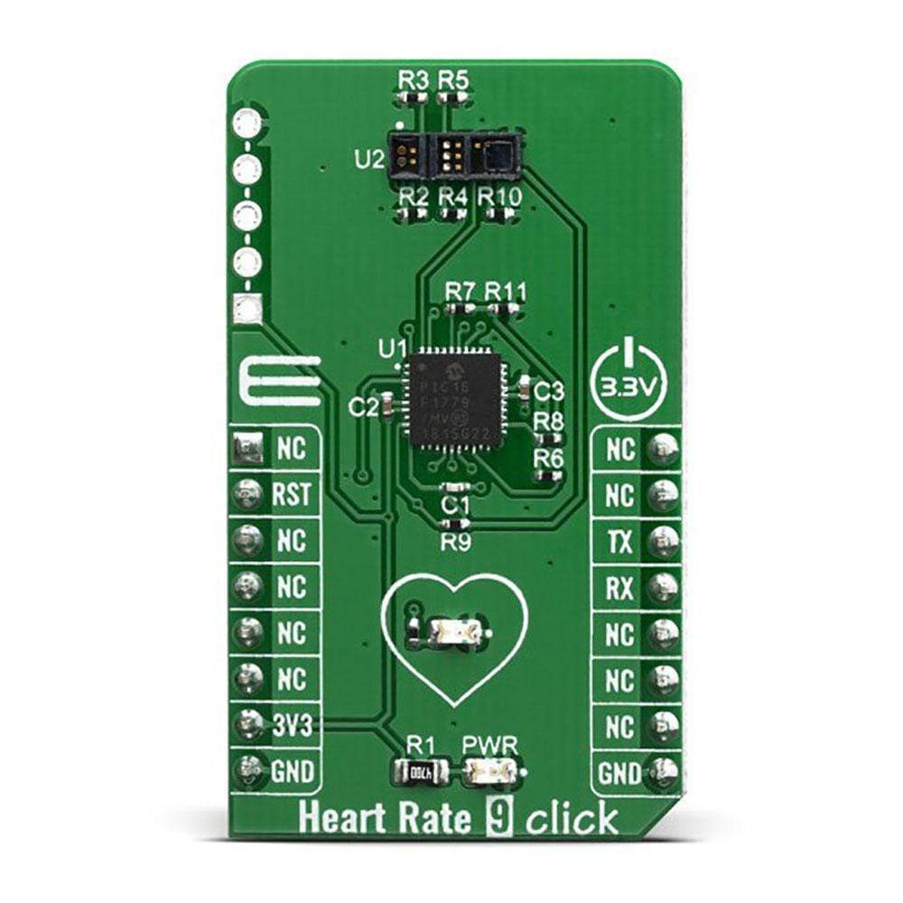
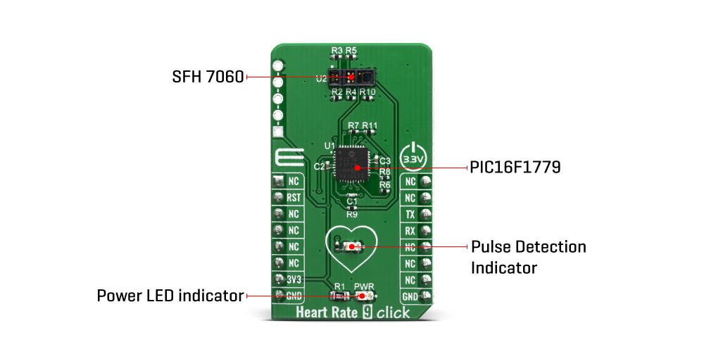
The Heart Rate 9 Click Board™ features the PIC16F1779 8-bit MCU and SFH 7060 heart rate and pulse oximetry monitoring sensor. This Click Board™ has an algorithm for processing data from the sensor and it can send data for 3 different diodes (Green, Infrared and Red) who give out a diagram of the heartbeat and its frequency per minute. The data has shown that the most notable signal comes from the green diode because it has the best reflection through the surface of the skin due to its shortest wavelength among three light sources. Implementing a light barrier to block optical crosstalk and improved geometry for optimized signal quality.
Most reflective heart rate monitors still have significant noise in their designs despite the use of complex and expensive analogue circuits such as Analog Front End (AFE) chips. A more cost-effective method for reducing noise and taking these measurements is necessary.
Downloads
How Does The Heart Rate 9 Click Board™ Work?
The Heart Rate 9 Click Board™ utilizes a Phase Division Multiplexing technique to simultaneously measure multiple signals with zero cross talk. This technique is implemented using the PIC16F1779 MCU's integrated Core Independent Peripherals (CIPs) from Microchip. Using the CIPs allows you to achieve a low-noise reflective heart rate monitor design with significantly lower BOM costs than conventional designs.
The Heart Rate 9 Click Board™ introduces Microchip's proprietary method (hereafter "proprietary method") of measuring multiple signals in a body using pseudorandom binary sequence generation and phase division multiplexing. This proprietary method uses a special encoding/decoding scheme to allow multiple light-emitting diodes (LED) transmitting light simultaneously with a single photodiode to condition each light from the combined lights at the receiving side.
While the blood passes through the capillary blood vessels, they expand and dilate. Their light reflectance index changes accordingly. This is the basis of the photo-plethysmogram (PPM), a method used for the volumetric measurement of an organ, or in this case - blood vessels. The heart rate signal is calculated according to the changes of the reflected green light, sensed by the PD element. The Heart Rate 6 Click Board™ can provide the HRM readings by simply placing the index finger over the optical sensor.
Oxygen saturation in the blood can be determined by measuring the light absorption in the red/IR part of the spectrum. The oxygen saturated blood absorbs more red light and less infrared than the unsaturated blood. This fact can be used to determine the oxygen saturation of the blood. For a healthy adult person, the peripheral capillary oxygen saturation (SpO2) percentage ranges from 95% to 100%.
The challenge in a multiple signal sources system (for example, the LEDs in the case of a pulse oximeter) is that each LED must share the same photodiode. A classic solution is to turn on each light source in sequence and then take each measurement in turn. Each light source gets its own slice of time in which the photodiode can get its measurement. This method is called Time-Division Multiplexing (TDM). The same principle is also applied to the TDMA-based cellular system. The drawback of the TDM approach is that adding more light sources, while keeping the data processing routine the same, results in more time to get a measurement from every source.
Microchip's proprietary method uses a known concept called Maximal Length (ML) sequence, a type of pseudorandom binary sequence, to generate a gold code or a reference sequence. This reference sequence is then phase shifted using Phase Division Multiplexing (PDM) to drive multiple LEDs. The light amplitudes from these LEDs, after passing through a part of a body, are detected by a phototransistor or photodiode and digitized with an Analog-to-Digital Converter (ADC). The digitized ADC light amplitude values are re-correlated with each LED's driving sequence. Spread spectrum techniques are known for their noise mitigation properties and ability to pass multiple signals through the same medium without interference. Thus, these measurements of each light absorption of the body can be performed substantially simultaneously with minimal interference from each other.
The SFH7060 made by OSRAM integrates three green, one red, one infrared emitter and one photodiode that are all placed in a reflective type of package. The reflective photosensing method has become increasingly popular in developing small, wearable biometric sensors, such as those green light sensors seen in the back of smart watches or activity tracker wristbands.
SPECIFICATIONS
| Type | Heart Rate,Biometrics |
| Applications | It can be used to develop applications based on the heart rate monitoring, pulse oximetry measurements, calorie expenditure, and similar health-related applications. |
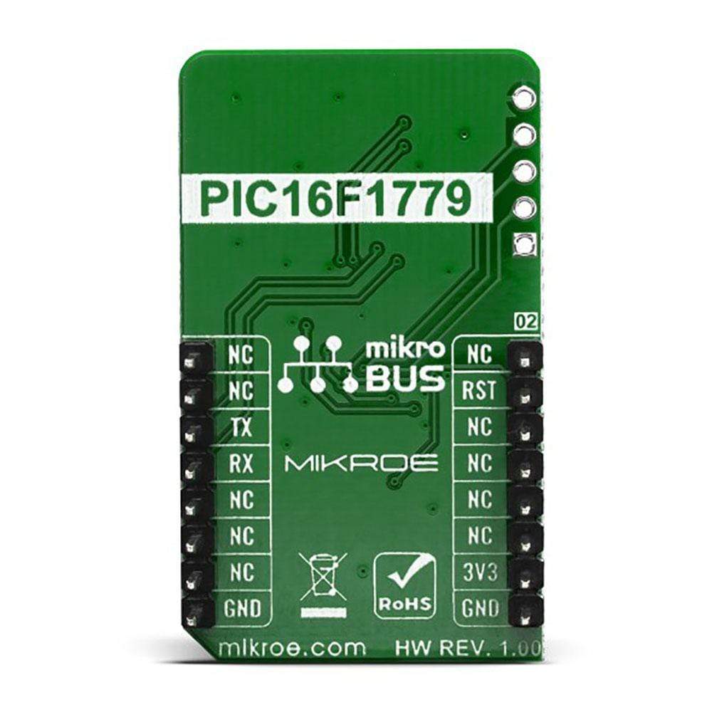
| On-board modules | PIC16F1779 MCU and SFH 7060 sensor |
| Key Features | Single-chip implementation using an eXtreme low-power (XLP) PIC16F1779 8-bit MCU, Integrated features of the 8-bit MCU use a Phase Division Multiplexing technique to simultaneously measure multiple signals with zero cross talk, Low overall BOM cost due to integrated Core Independent Peripherals ( CIPs) and Analog features, Core Independent Peripherals reduce software overheard. |
| Interface | GPIO,UART |
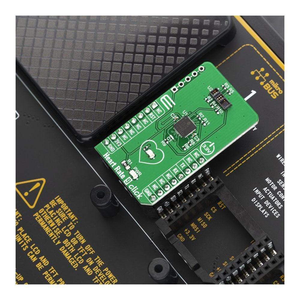
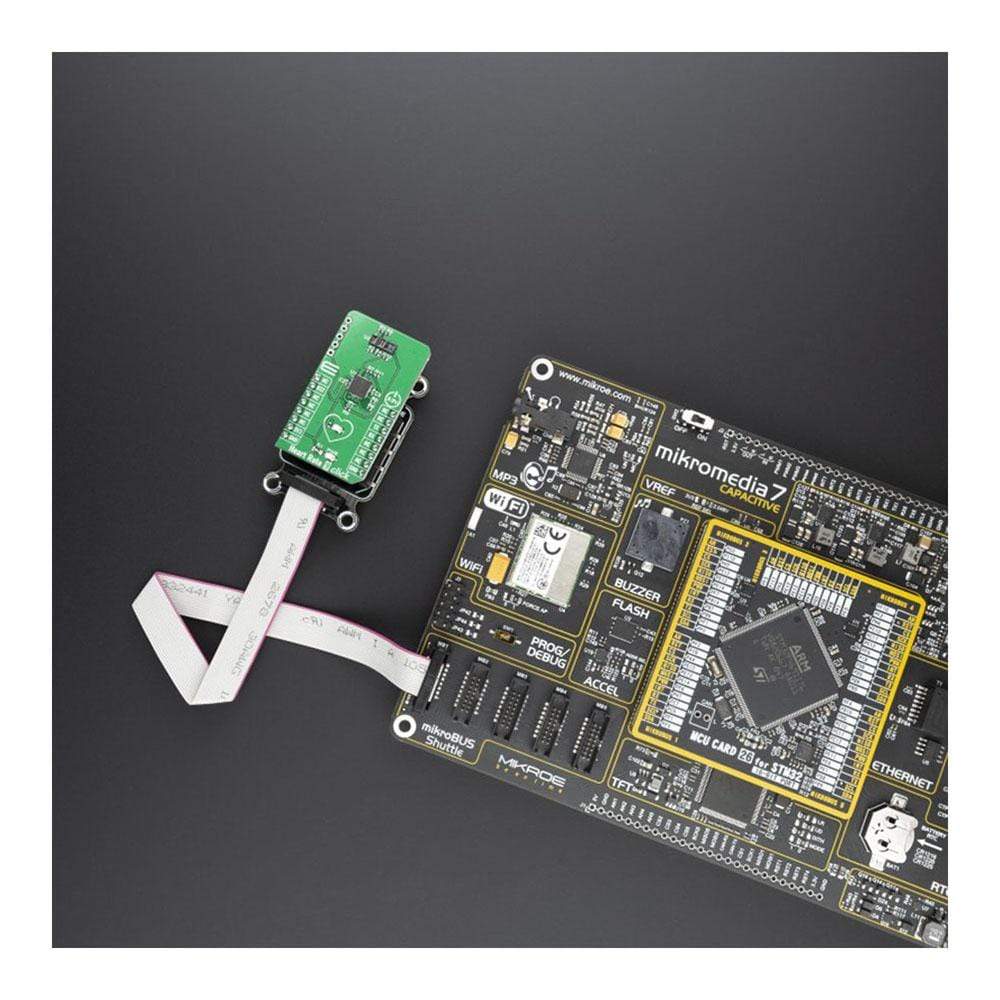
| Compatibility | mikroBUS |
| Click Board™ size | M (42.9 x 25.4 mm) |
| Input Voltage | 3.3V |
PINOUT DIAGRAM
This table shows how the pinout on the Heart Rate 9 Click Board™ corresponds to the pinout on the mikroBUS socket (the latter shown in the two middle columns).
| Notes | Pin | Pin | Notes | ||||
|---|---|---|---|---|---|---|---|
| NC | 1 | AN | PWM | 16 | NC | ||
| Reset | RST | 2 | RST | INT | 15 | NC | |
| NC | 3 | CS | RX | 14 | TX | UART Transmit | |
| NC | 4 | SCK | TX | 13 | RX | UART Receive | |
| NC | 5 | MISO | SCL | 12 | NC | ||
| NC | 6 | MOSI | SDA | 11 | NC | ||
| Power Supply | 3.3V | 7 | 3.3V | 5V | 10 | NC | |
| Ground | GND | 8 | GND | GND | 9 | GND | Ground |
ONBOARD SETTINGS AND INDICATORS
| Label | Name | Default | Description |
|---|---|---|---|
| LD1 | PWR | - | Power LED Indicator |
| LD2 | RED | - | Pulse Detection Indicator |
| General Information | |
|---|---|
Part Number (SKU) |
MIKROE-3822
|
Manufacturer |
|
| Physical and Mechanical | |
Weight |
0.018 kg
|
| Other | |
EAN |
8606018719709
|
Frequently Asked Questions
Have a Question?
Be the first to ask a question about this.