


Mikroelektronika d.o.o.
Heart Rate 8 Click Board™
Heart Rate 8 Click Board™
SKU: MIKROE-3218
Couldn't load pickup availability

Overview
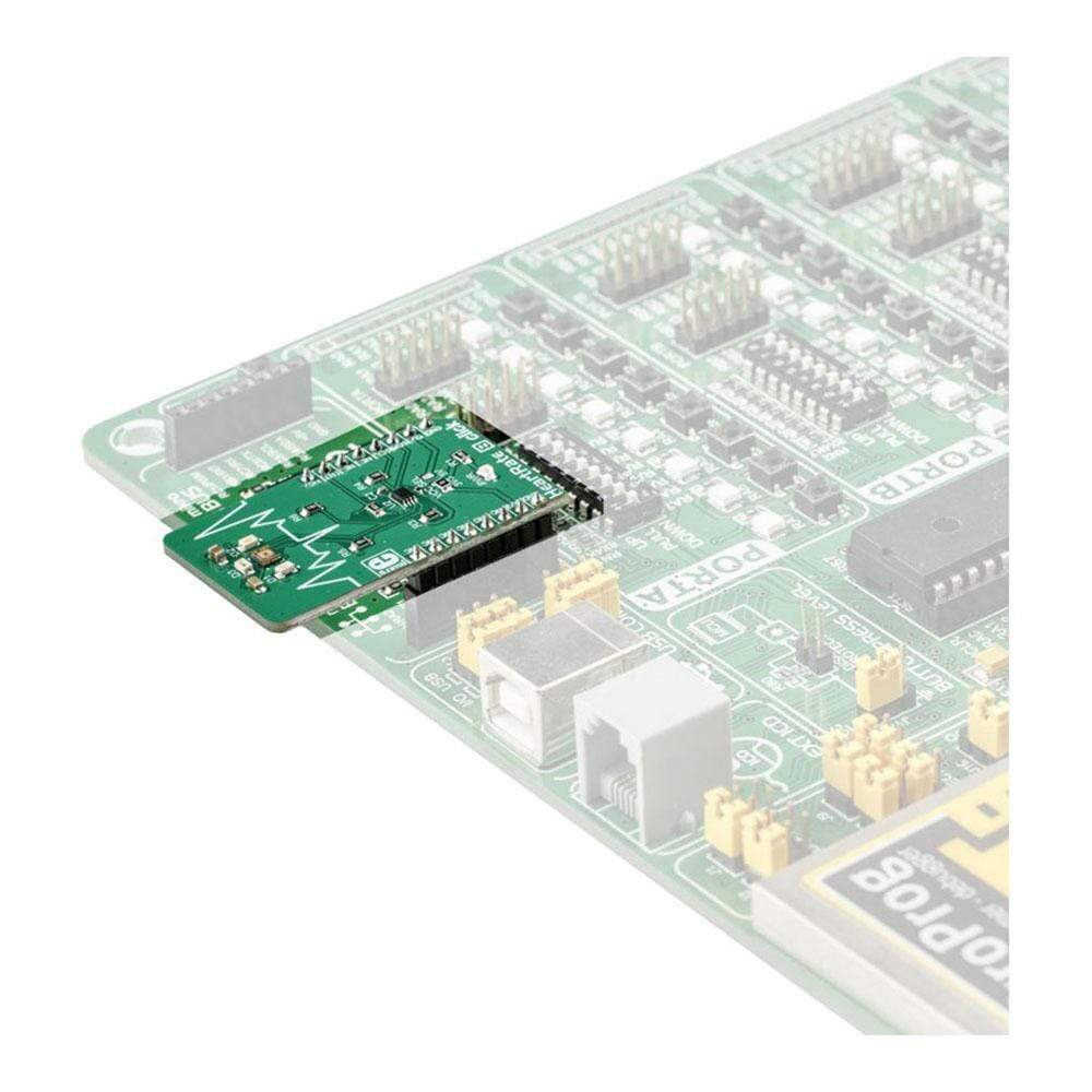
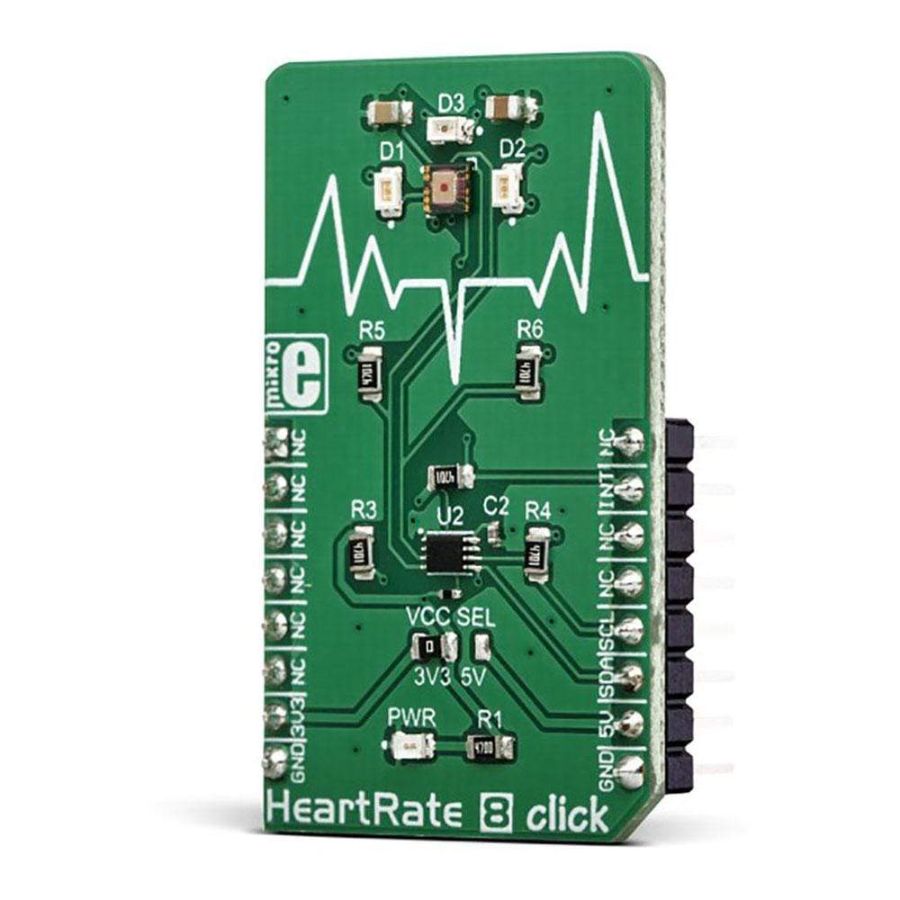
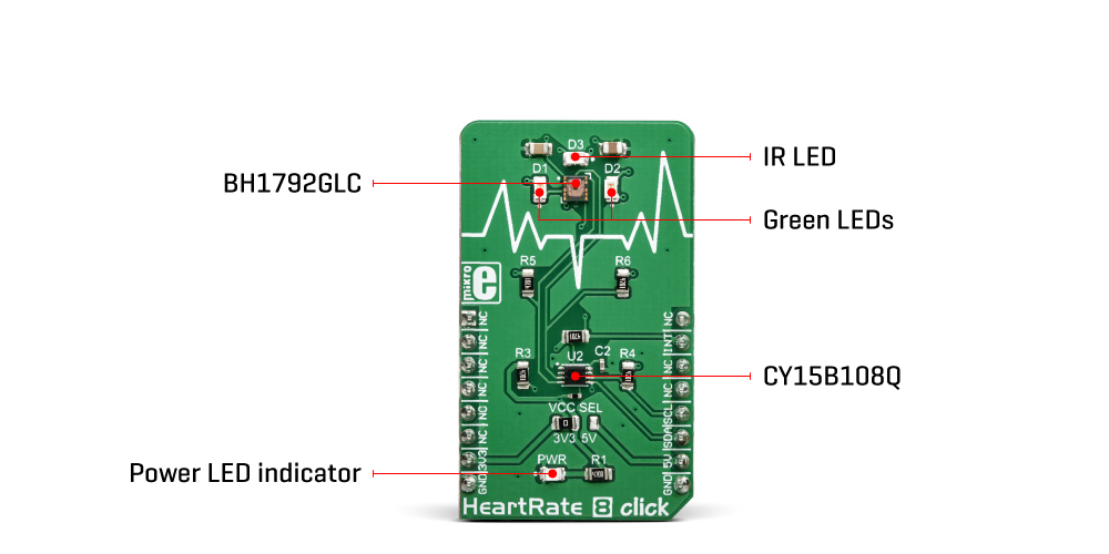
The Heart Rate 8 Click Board™ is an optical biosensor, designed for heart-rate monitoring (HRM). This Click Board™ employs a specialised sensor that incorporates three LED drivers and two photo-sensing elements, sensitive to green and IR light. The green light is most commonly used to measure the dilatation of the blood vessels; therefore, the Heart Rate 8 Click Board™ is equipped with two green LEDs, which are driven by the BH1792GLC, a monolithic integrated sensor for heart rate monitoring, and the additional IR LED, used to detect a finger touch. The Heart Rate 8 Click Board™ is a perfect solution for the development of various wearable health-related devices, smartphones, tablets, and similar space-constrained applications.
It comes in a package that also includes the mikroSDK software and a library with all the functions. The Click Board™ comes as a fully tested and approved prototype, making it a reliable device ready to use on the development board.
Downloads
One IR and two green LEDs are driven by the BH1792GLC sensor, which provides a constant, programmable current. The choice of LEDs is not critical at all, since the integrated light filters on the sensor allow only a narrow band of green light in the range from 520nm to 560nm with 0.8X reduction in respect to the centre frequency (about 540nm). The complete monolithic integrated solution with three constant current LED drivers, narrow bandpass for the green light spectrum, IR detection, low power consumption, and a high integration ratio that allows a very low number of external components, make the Heart Rate 8 Click Board™ a perfect solution for the development of various wearable health-related devices, smart phones, tablets, and similar space-constrained applications.
HEART RATE MONITORING OR HRM
While the blood passes through the capillary blood vessels, they expand and dilate. Their light reflectance index changes accordingly. This is the basis of the photo-plethysmogram (PPM), a method used for the volumetric measurement of an organ, or in this case - blood vessels. The heart rate signal is calculated according to the changes of the reflected green light, sensed by the PD element. The Heart Rate 8 click can provide the HRM readings by simply placing the index finger over the optical sensor.
How Does The Heart Rate 8 Click Board™ Work?
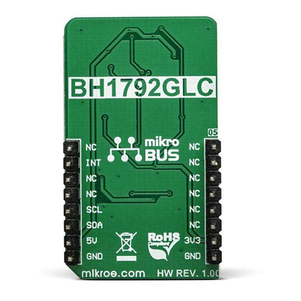
The Heart Rate 8 Click Board™ is equipped with the BH1792GLC, a monolithic integrated sensor for heart rate monitoring, from ROHM Semiconductor company. This IC is a highly integrated optical sensor, very well suited for performing PPM measurements. Due to the large integration scale of this sensor, as well as its low power consumption, it is perfectly suited to be used on a wearable IoT device. However, being a Click board™, Heart rate 8 click allows easy evaluation and rapid application and firmware development.
Two green LEDs are driven by the integrated LED driving section of the BH1790GLC sensor, with the programmable Synchronized Measurement mode, with the measuring frequency between 32Hz and 1024Hz. While in this mode, two green LEDs will operated at various frequencies between 32Hz and 1024Hz, depending on the MSR bits of the measurement mode register. This allows automatic LED burst rate adjustment for achieving optimal readings. In this mode, a programmed number of measurements will be performed, and the readings will be stored on the 35 samples deep FIFO buffer. LED current can be programmed in the range from 0 to 63 mA, providing another layer of control while using this mode. The measurement is performed upon receiving the MEAS_SYNC command by setting the MEAS_SYNC bit to logic 1.
There are also two additional modes: Non-Synchronized, and Single Measurement mode, both allowing the use of the IR LED to detect an IR emitting object, such as the hand, or finger. The current through the LEDs can also be programmed in the range from 0 to 63mA, for both the IR and the green LEDs. Non-Synchronized mode offers a fixed 4 Hz LED burst operation, while the Single Measurement mode allows manual control of all the parameters. No data will be stored on the FIFO buffer in thisi mode. The measurement is performed upon receiving the MEAS_ST command by setting the MEAS_ST bit to logic 1.
The reflected light burst is detected by a sensing element in a form of a photo-diode, sampled by a low noise 16-bit A/D converter. The photo-diodes are located behind two light filters which pass only a narrow band of green light in the range from 520nm to 560nm, with 0.8X reduction in respect to the center frequency. The top filter is an IRCUT filter, that prevents the influence of the IR light, while the second filtering layer only passes the green light. This allows even broader color range LEDs to be used, reducing the overall cost of the design. However, the Heart Rate 8 Click Board™ uses a pair of specialized green LEDs, with the spectral response that is closely matched to the passband properties of the optical filter. This allows most of the LED energy to be used, further improving the power consumption profile.
The second A/D converter does not have any light filtering, allowing the light coming from the IR diode to be sensed. This is useful when a separate detection of the IR spectrum is required, for example to detect an approach of the finger. The IR LED driver is physically shared with the second green LED driver, but the IR LED has its own dedicated pin.
Two sets of four output registers contain the 16-bit measurement data in a form of two 8-bit words, for the measurement when the LEDs are ON and when the LEDs are OFF. The upper and the lower 8-bit registers contain the measurement data which can be retrieved over the standard I2C interface. The datasheet of the BH1792GLC contains the correct algorithms which describe the measurement process with more details. However, the Click board™ comes with the library which contains functions that allow measurements to be performed with minimum efforts.
A dedicated programmable INT pin can be used to signal an interrupt to the host MCU. The interrupt can be triggered for several different events, including the data ready event (measurement completed), an event when the IR threshold is exceeded, and so-called watermark event which occurs when the FIFO buffer is nearly full. It can also be completely disabled. The INT pin is routed to the INT pin of the mikroBUS™.
A low number of external components required by the BH1792GLC sensor, allows enough room on the Heart Rate 8 Click Board™ for the PCA9306 IC, a well-known I2C level translator, allowing the Heart rate 8 click to be interfaced with many different MCUs, both operating with 3.3V and 5V logic levels.
SPECIFICATIONS
| Type | Biometrics,Heart Rate |
| Applications | The Heart Rate 8 Click Board™ is an ideal solution for the development of various wearable health-related devices, smart phones, tablet PC, etc. |
| On-board modules | BH1792GLC, a monolithic integrated sensor with I2C interface for heart rate monitoring, from ROHM Semiconductor company |
| Key Features | A complete heart rate measurement solution with constant current LED drivers, built-in photo diodes with filtering for both green and IR light spectrum, high integration ratio allowing a low number of external components, FIFO buffer for storing up to 35 samples, and more. |
| Interface | I2C |
| Compatibility | mikroBUS |
| Click board size | M (42.9 x 25.4 mm) |
| Input Voltage | 3.3V or 5V |
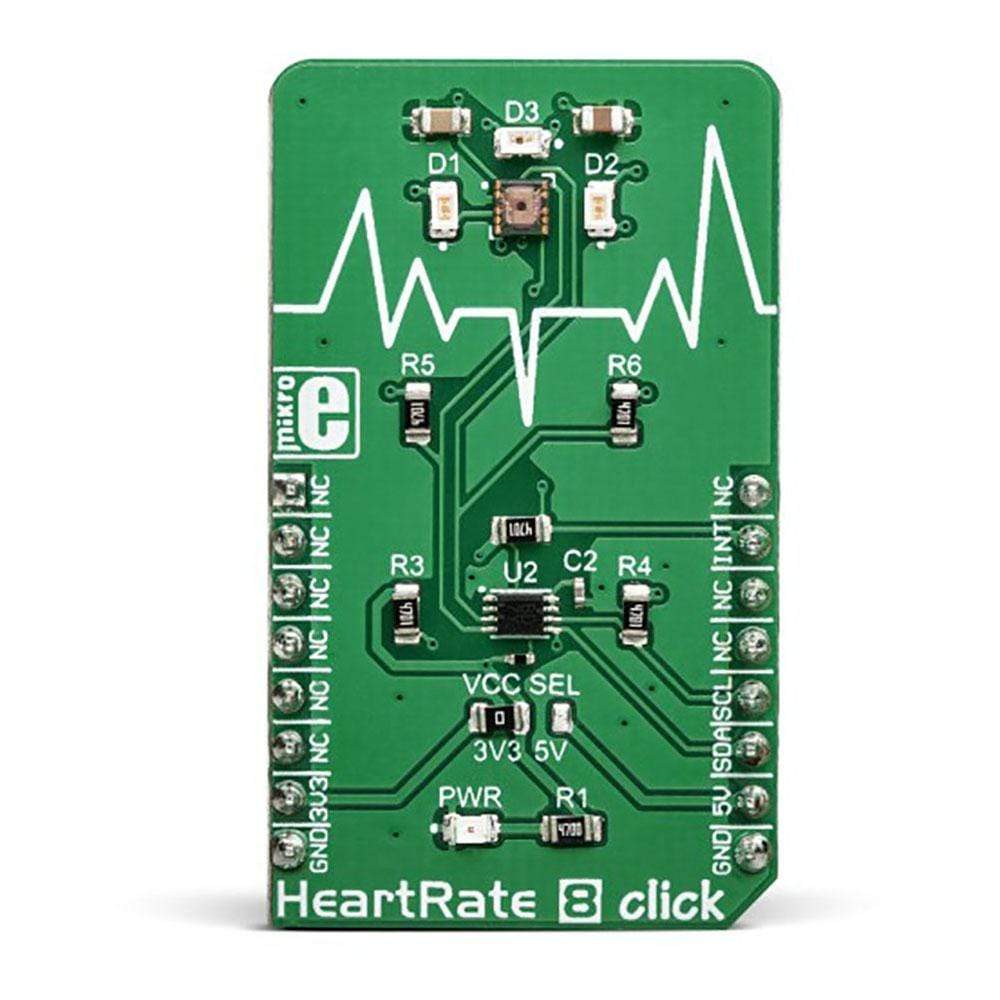
PINOUT DIAGRAM
This table shows how the pinout on the Heart Rate 8 Click Board™ corresponds to the pinout on the mikroBUS™ socket (the latter shown in the two middle columns).
| Notes | Pin | Pin | Notes | ||||
|---|---|---|---|---|---|---|---|
| NC | 1 | AN | PWM | 16 | NC | ||
| NC | 2 | RST | INT | 15 | INT | Interrupt | |
| NC | 3 | CS | RX | 14 | NC | ||
| NC | 4 | SCK | TX | 13 | NC | ||
| NC | 5 | MISO | SCL | 12 | SCL | I2C Clock | |
| NC | 6 | MOSI | SDA | 11 | SDA | I2C Data | |
| Power supply | 3V3 | 7 | 3.3V | 5V | 10 | 5V | Power supply |
| Ground | GND | 8 | GND | GND | 9 | GND | Ground |
ONBOARD SETTINGS AND INDICATORS
| Label | Name | Default | Description |
|---|---|---|---|
| PWR | PWR | - | Power LED indicator |
| VCC SEL | VCC SEL | Left | Logic voltage level selection: left position 3.3V, right position 5V |
| General Information | |
|---|---|
Part Number (SKU) |
MIKROE-3218
|
Manufacturer |
|
| Physical and Mechanical | |
Weight |
0.019 kg
|
| Other | |
EAN |
8606018713745
|
Frequently Asked Questions
Have a Question?
Be the first to ask a question about this.