


Hantek Electronic Co Ltd
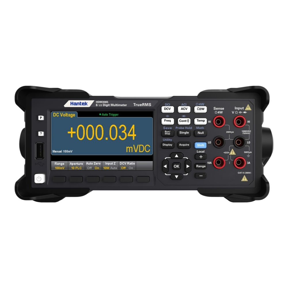
Hantek HDM3065 6½ Digit TrueRMS Digital Multimeter
Hantek HDM3065 6½ Digit TrueRMS Digital Multimeter
SKU: HDM3065
Couldn't load pickup availability


Overview
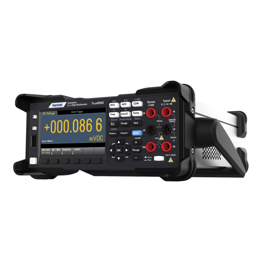
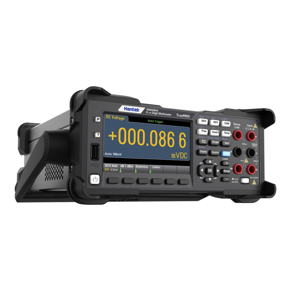
The Hantek HDM3065 series 6½ digit bench multimeter is a brand-new addition to the Hantek family. Based on modern styling, it would be a proud addition to the bench of any electronic engineer. It offers excellent value.
The enhanced resolution and its superb reading rate make this multimeter ideal for capturing transient signals with accuracy.
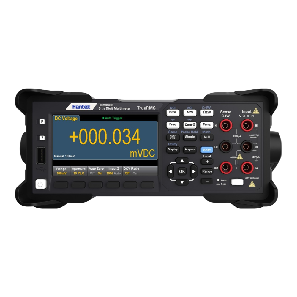
The multimeter is based on a 4.3", 64K colour LCD display with a dual-display of measured signals in two different formats.
The HDM3065 can also be controlled from a host PC with the supplied PC software.
Downloads
Features
- Real 6 1/2 bit reading resolution;
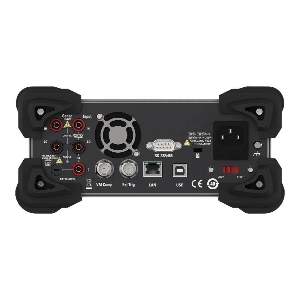
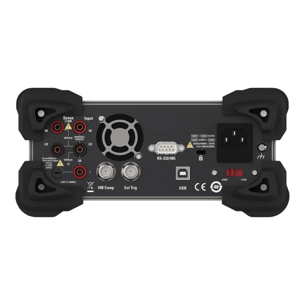
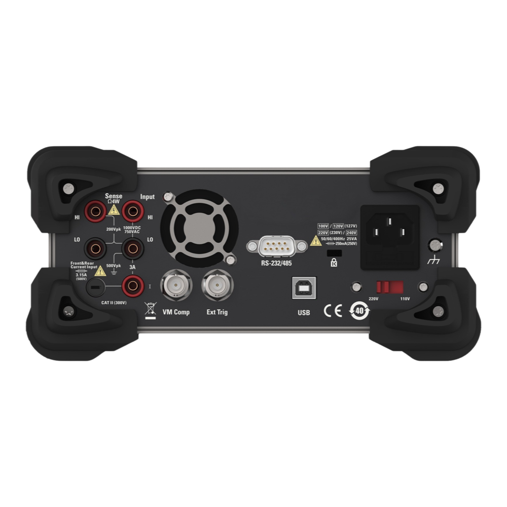
- Front and back two sets of multimeter input interface, the measure can a key switch;
- Up to 30,000 rdgs/s reading;
- Graph display function, trend drawing function to paperless record testing data, statistic information and histogram;
- Double display measurement function, display 2 kinds of signal parameters at the same time;
- True RMS AC voltage and AC current measure;
- 0.1μV resolution, easy to use, parameters can be set easily;
- Support dual display, Chinese and English menu;
- The built-in help system, convenient access to information;
- 13 kinds of measure functions: DC Voltage, AC Voltage, DC current, AC current, 2 line resistance, 4 line resistance, capacitance, diode, connectivity, frequency, period, current range can be 10A;
- 4.3 inch 64K LCD;
- Safety standards: CAT II 300 V;
- Support standard SCPI Remote control command、upper computer software、Compatible with the latest mainstream multimeter command set;
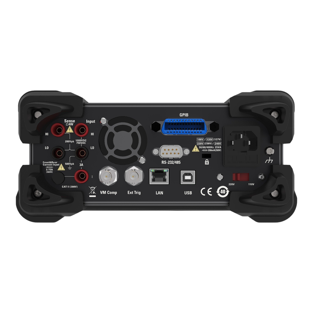
- Configuration interface: USB Device, USB Host, LAN (HDM3065B), GPIB (HDM3065H).
DC Voltage Accuracy ± (% reading + % range) |
||||
| Range1/Frequency | Test current or Load voltage | Input impedance | 1 year | Temperature coefficient/°C |
| 23℃± 5 °C | 0 ℃-18 ℃ | |||
| DC voltage | 28 ℃-55 ℃ | |||
| 100 mV | — | 10 MΩ or>10 GΩ | 0.018 + 0.008 | 0.0020 + 0.0008 |
| 1 V | — | 10 MΩor>10 GΩ | 0.015 + 0.005 | 0.0015 + 0.0008 |
| 10 V | — | 10 MΩ | 0.015 +0.005 | 0.0020 + 0.0008 |
| 100 V | — | 10 MΩ | 0.015 + 0.005 | 0.0020 + 0.0008 |
| 1000 V | — | 10 MΩ | 0.015 + 0.005 | 0.0020 + 0.0008 |
Resistance2 |
||||
| 100 Ω | 1 mA | — | 0.050 + 0.008 | 0.0060 + 0.0008 |
| 1k Ω | 1 mA | — | 0.050 + 0.008 | 0.0060 + 0.0005 |
| 10 kΩ | 100 μA | — | 0.050 + 0.005 | 0.0060 + 0.0005 |
| 100 kΩ | 10 μA | — | 0.050 + 0.005 | 0.0060 + 0.0005 |
| 1 MΩ | 5 μA | — | 0.060 + 0.005 | 0.0060 + 0.0005 |
| 10 MΩ | 500 nA | — | 0.250 + 0.005 | 0.0250 + 0.0005 |
| 100 MΩ | 500 nA || 10 MΩ | — | 2.000 + 0.005 | 0.3000 + 0.0005 |
| DC | ||||
| 100 μA | <0.02 V | — | 0.050 + 0.015 | 0.007 + 0.0015 |
| 1 mA | <0.2 V | — | 0.050 + 0.007 | 0.007 + 0.0010 |
| 10 mA | <0.02 V | — | 0.050 + 0.015 | 0.008 + 0.0015 |
| 100 mA | <0.2 V | — | 0.050 + 0.007 | 0.008 + 0.0010 |
| 1 A | <0.1 V | — | 0.100 + 0.015 | 0.012 + 0.0015 |
| 3 A | <0.3 V | — | 0.250 + 0.007 | 0.015 + 0.0010 |
| 10 A | <0.02 V | — | 0.250 + 0.007 | 0.015 + 0.0010 |
Breakover3 |
||||
| 1 kΩ | 1 mA | — | 0.100 + 0.100 | 0.005 + 0.005 |
Diode Test4 |
||||
| 5 V | 1 mA | — | 0.05 + 0.03 | 0.005 + 0.005 |
AC Voltage Accuracy ± (% reading + % range) |
||||
| True RMS AC voltage 5,6 | Test current or Load voltage | Input impedance | 1 year | Temperature coefficient/°C |
| 23 ℃± 5 °C | 0 ℃-18 ℃ | |||
| 28 ℃-55 ℃ | ||||
| 100 mV Range | ||||
| 20 Hz-45 Hz | — | — | 1.00 + 0.10 | 0.02 + 0.02 |
| 45 Hz-10 kHz | — | — | 0.20 + 0.10 | 0.02 + 0.02 |
| 10 kHz-30 kHz | — | — | 1.50 + 0.30 | 0.05 + 0.02 |
| 30 kHz-100 kHz7 | — | — | 3.00 + 0.30 | 0.10 + 0.02 |
| Range: 1 V, 10 V, 100 V and 750 V | ||||
| 20 Hz-45 Hz | — | — | 1.00+0.108 | 0.02+0.02 |
| 45 kHz-10 kHz | — | — | 0.20+0.10 | 0.02+0.02 |
| 10 kHz-30 kHz | — | — | 1.50+0.30 | 0.05+0.02 |
| 30 kHz-100 kHz3 | — | — | 3.00+0.309 | 0.10+0.02 |
True RMS AC Current2 |
||||
| Range: 100 uA-10 A | ||||
| 20Hz-45 Hz | — | — | 1.50 + 0.10 | 0.02+0.02 |
| 45Hz-1 kHz | — | — | 0.50 + 0.10 | 0.02+0.02 |
| 1 kHz-10 kHz10 | — | — | 2.00 + 0.20 | 0.02+0.02 |
Frequency Accuracy ±(% reading+3 counts) |
||||
| Frequency range11 : 100 mV,1 V,10 V,100 V and 750 V | ||||
| 20 Hz – 300 kHz12 | — | — | 0.02+3 | 0.005 |
| Frequency resolution | Frequency | Resolution | ||
| Range13: 100 mV,1 V,10 V,100 V and 750 V | 119.999 Hz | 0.001 Hz | ||
| 1.19999 kHz | 0.00001 kHz | |||
| 11.9999 kHz | 0.0001 kHz | |||
| 119.999 kHz | 0.001 kHz | |||
| 1.00000 MHz | 0.00001 MHz | |||
Capacitance1 |
Test current or probe type | Input impedance | 1 year | Temperature coefficient/°C |
| 23 ℃± 5 °C | 0 ℃-18 ℃ | |||
| 28 ℃-55 ℃ | ||||
| 1.000 nF | 5 μA | — | 1. + 0.5 | 0.02 + 0.001 |
| 10.00 nF | 5 μA | — | 1 + 0.5 | 0.02 + 0.001 |
| 100.0 nF | 10 μA | — | 1 + 0.5 | 0.02 + 0.001 |
| 1.000 μF | 100 μA | — | 1 + 0.5 | 0.02 + 0.001 |
| 10.000 μF | 1 mA | — | 1 + 0.5 | 0.02 + 0.001 |
| 100.00 μF | 1 mA | — | 1 + 0.5 | 0.02 + 0.001 |
Technical indicators are valid in the following cases: preheating for 90 minutes, setting integral time to 10 or 100NPLC, enabling automatic zero. The temperature for the calibration should be within 18℃-28℃.
1. Except for 1000DCV and 3A/10ADC, all ranges have a 20% overrange.
2. Technical indicators are suitable for 4-wire or 2-wire resistance measurement. However, if not pressing the "Null" key ahead of time to eliminate the offset, 2-wire resistance measurement will increase 0.2Ω additional error.
3. Continuous threshold value is fixed less than 10Ω and only available in the fast measurement mode.
4. Technical indicators are only suitable for the voltage measured at the input terminal and only available in the fast measurement mode.
5. Except for 750VAC and ACI 3A/10A, all ranges have a 20% overrange.
6. If the measuring range is not 750V, technical indicators are valid only if the input signal is a sinusoidal signal and the amplitude of is >5% of the current measurement range.
When adopting the 750 V range, the input signal must be greater than 50Vrms.
7. When the input signal frequency is > 30 KHz and the input signal amplitude < 10% of the current measuring range, an additional error will occur. If the frequency is 30 KHz ~ 100KHz, each 1kHz will increase the additional error by 0.003%of the range.
8. Input < 200Vrms
9. Input < 300Vrms
10. The technical indicators are suitable when frequency < 5 kHz. The frequency which >= 5KHz is a typical value.
11. Frequencies up to 1 MHz can be measured when 0.5Vrms signal inputs at the 100 mV / 1 V gear.
12. Technical Indicators are suitable for all ranges when input signal > 10% of the range except for specially specified ranges. The technical indicators for the 100mV range can only be applied when the input signal is between 100 mV to 120 mV. When the input signal is between 10mV and 100mV, the indicator number should be multiplied by 10.
13. Frequency up to 1 MHz can be measured when 0.5Vrmsignal input is at the 100 mV / 1 V range.
| General Information | |
|---|---|
Part Number (SKU) |
HDM3065
|
| Physical and Mechanical | |
Weight |
3.8 kg
|
| Other | |
EAN |
5055383620333
|
Frequently Asked Questions
Have a Question?
-
Does it come with a calibration certificate?
Yes, the HDM3065 comes with a basic calibration certificate.