Overview
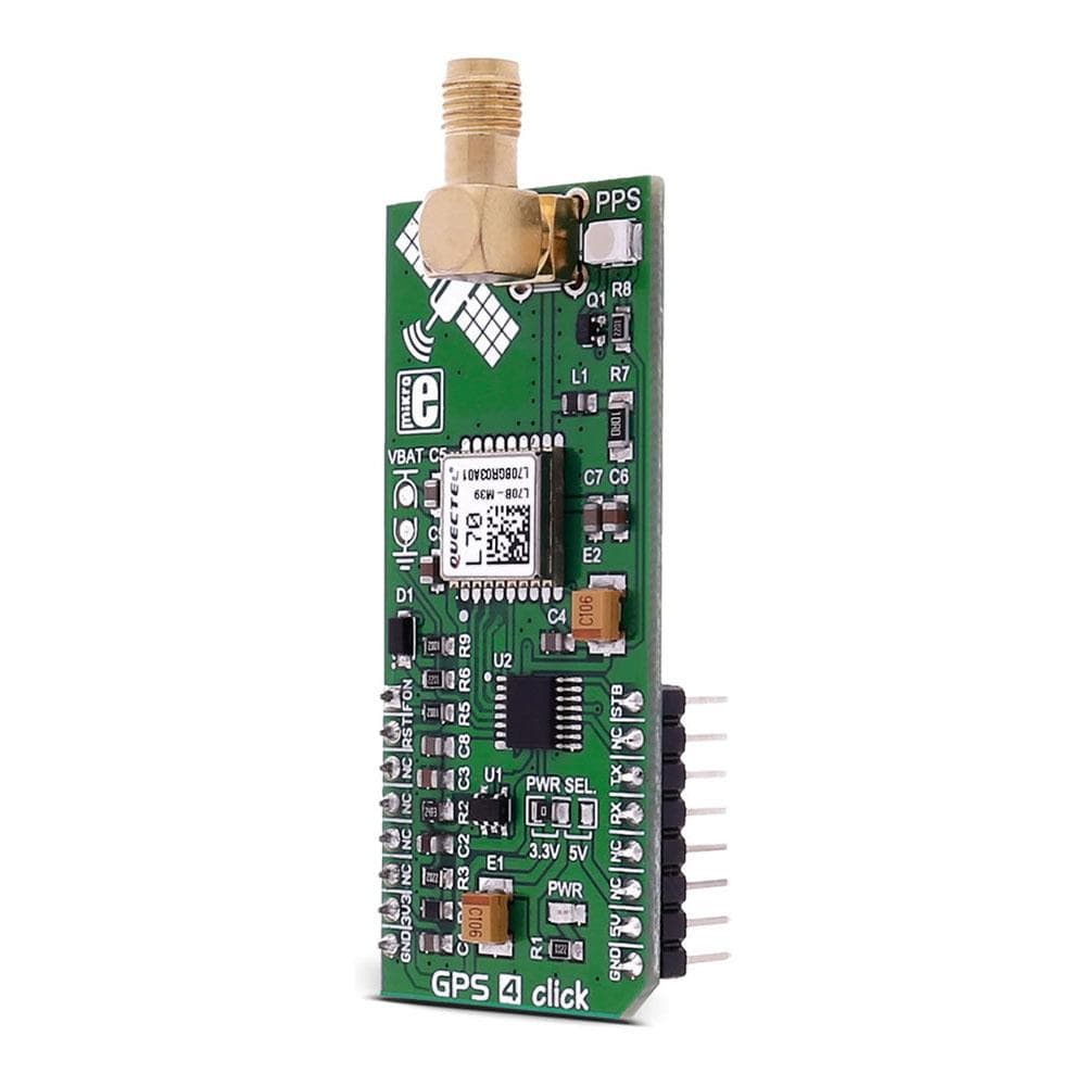
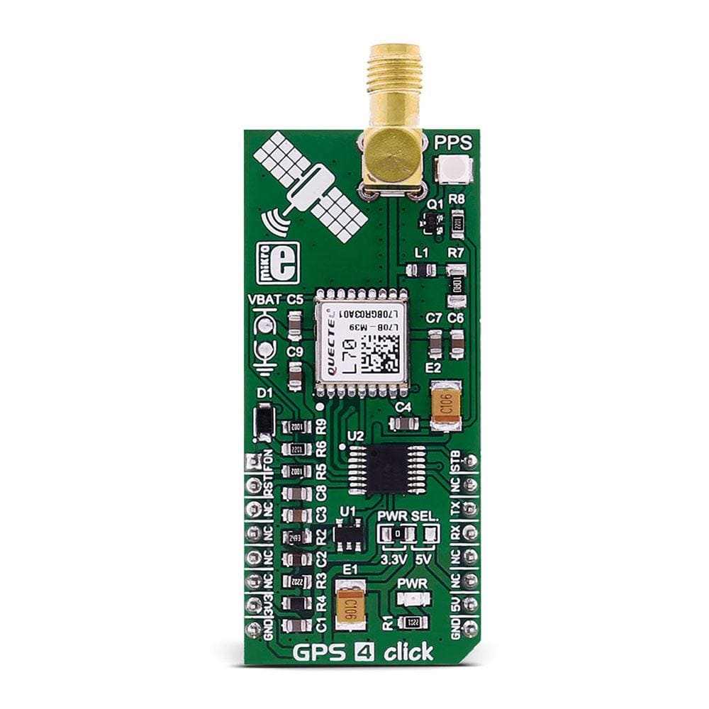
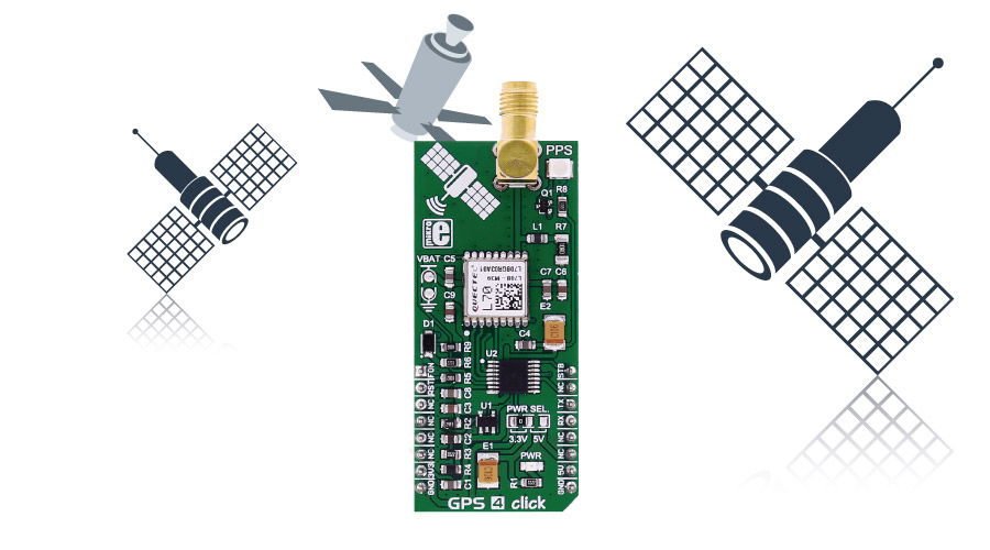
The GPS 4 Click Board™ carries the L70 compact GPS module from Quectel. The Click Board™ is designed to run on either a 3.3V or 5V power supply.
It communicates with the target microcontroller over the UART interface, with additional functionality provided by the following pins on the MikroBUSline: PWM, AN, RST.
Downloads
The GPS 4 Click Board™ carries the L70 compact GPS module from Quectel. The click is designed to run on either 3.3V or 5V power supply. It communicates with the target microcontroller over UART interface, with additional functionality provided by the following pins on the mikroBUS™ line: PWM, AN, RST.
L70 MODULE FEATURES
L70, an SMD type module, brings the high performance of MTK positioning engine to the industrial applications with a compact profile, ultra low power consumption and fast positioning capability.
Combining advanced AGPS called EASY™ (Embedded Assist System) and proven AlwaysLocate™ technology, L70 achieves the highest performance and fully meets the industrial standard. EASY™ technology ensures L70 can calculate and predict orbits automatically using the ephemeris data (up to 3 days) stored in internal RAM memory, so L70 can fix position quickly even at indoor signal levels with low power consumption.
With AlwaysLocate™ technology , L70 can adaptively adjust the on/off time to achieve a balance between positioning accuracy and power consumption according to the environmental and motion conditions.
How Does The GPS 4 Click Board™ Work?
A constellation of satellites sends a continuous signal towards Earth. Onboard every satellite is an atomic clock, and all of them are synchronized, thanks to a reference time scale defined by the whole system. So, that the signals coming from the different satellites of the same constellation share the same reference time scale.
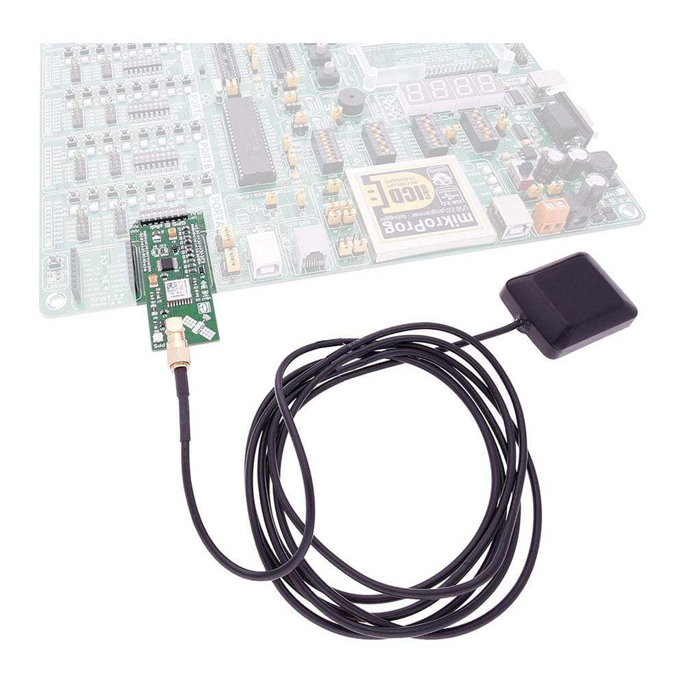
The user wanting to use GPS to determine its position must have an antenna that receives the signals coming from the satellites, and a receiver that translates these signals. The antenna position will be deduced from the measurements of the time delay between the emission time (satellite) and the reception time (receiver) for at least 4 signals coming from different satellites.
SPECIFICATIONS
| Type | GPS+GNSS |
| Applications | Navigation devices based on GPS |
| On-board modules | Quectel's L70 |
| Key Features | Ultra low power consumption in tracking mode, 12mA, High sensitivity, -165dBm@Tracking, -148dBm@Acquisition |
| Interface | UART |
| Compatibility | mikroBUS |
| Click board size | L (57.15 x 25.4 mm) |
| Input Voltage | 3.3V or 5V |
PINOUT DIAGRAM
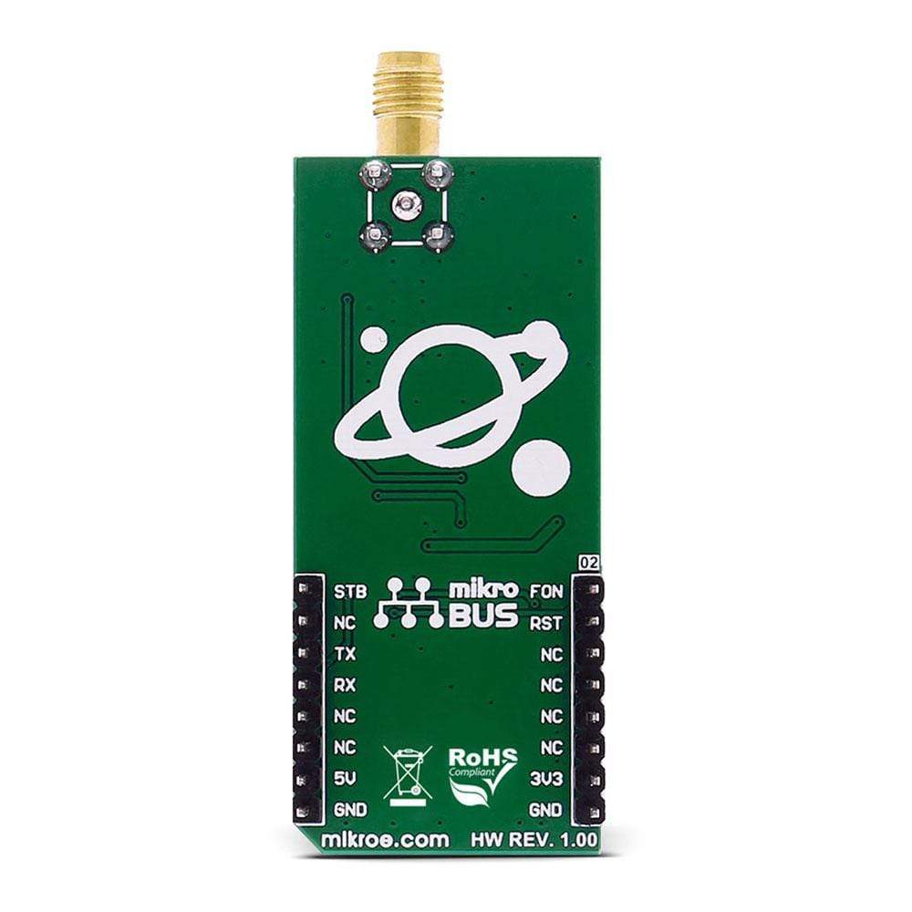
This table shows how the pinout on the GPS 4 Click Board™ corresponds to the pinout on the mikroBUS™ socket (the latter shown in the two middle columns).
| Notes | Pin |  |
Pin | Notes | |||
|---|---|---|---|---|---|---|---|
| Module Force ON | FORCE ON | 1 | AN | PWM | 16 | STANDBY | Module Standby |
| Module Reset | RST | 2 | RST | INT | 15 | NC | |
| NC | 3 | CS | TX | 14 | TX | Module Transmit line | |
| NC | 4 | SCK | RX | 13 | RX | Module Receive line | |
| NC | 5 | MISO | SCL | 12 | NC | ||
| NC | 6 | MOSI | SDA | 11 | NC | ||
| Power supply | +3.3V | 7 | 3.3V | 5V | 10 | +5V | Power supply |
| Ground | GND | 8 | GND | GND | 9 | GND | Ground |
JUMPERS AND SETTINGS
| Designator | Name | Default Position | Default Option | Description |
|---|---|---|---|---|
| JP1 | VBAT | ON | VCC | BCKP Battery connection |
| JP2 | VCCIO | 3V3 | Level selector |
BUTTONS AND LEDS
| Designator | Name | Type | Description |
|---|---|---|---|
| LD1 | PWR | LED | Power Indication LED |
| LD2 | PPS | LED | GPS tracking indicator |
| General Information | |
|---|---|
Part Number (SKU) |
MIKROE-2704
|
Manufacturer |
|
| Physical and Mechanical | |
Weight |
0.03 kg
|
| Other | |
Country of Origin |
|
HS Code Customs Tariff code
|
|
EAN |
8606018710980
|
Warranty |
|
Frequently Asked Questions
Have a Question?
Be the first to ask a question about this.

