

Mikroelektronika d.o.o.
Fingerprint 3 Click Board™
Fingerprint 3 Click Board™
SKU: MIKROE-4265
Couldn't load pickup availability


Overview
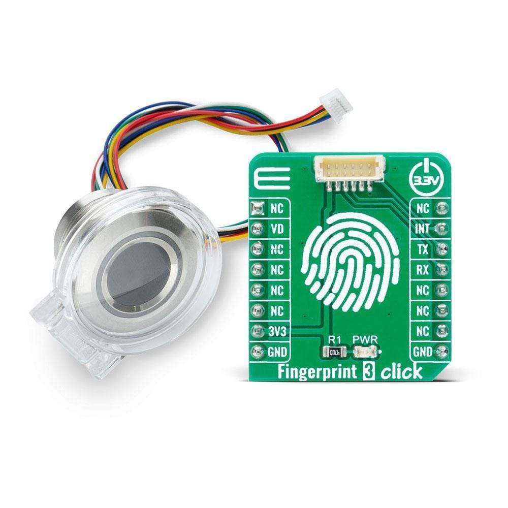
The Fingerprint 3 Click Board™ is an adapter Click Board™, used to interface a compatible Fingerprint Sensor with Two-Color LED Ring with the host MCU. This Click Board™ allows users to secure their projects with a biometric all-in-one fingerprint sensor that will make fingerprint detection and verification super simple. There is a wide range of applications, where Fingerprint 3 Click can be implemented: it can be embedded into a variety of end products such as access control, attendance, or safety deposit box which allows the user to integrate biometric security into its design in the easiest and fastest way.
Fingerprint 3 Click is supported by a mikroSDK compliant library, which includes functions that simplify software development. This Click Board™ comes as a fully tested product, ready to be used on a system equipped with the mikroBUS™ socket.
NOTE: The sensor does not come in the same package as this Click Board™. Please visit the Fingerprint 3 Click bundle page for a complete package.
Downloads
How Does The Fingerprint 3 Click Board™ Work?
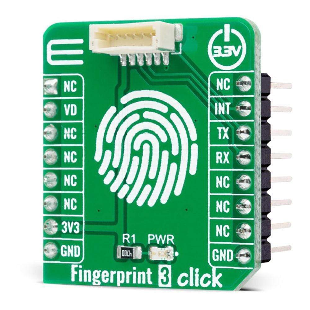
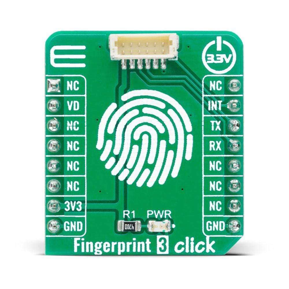
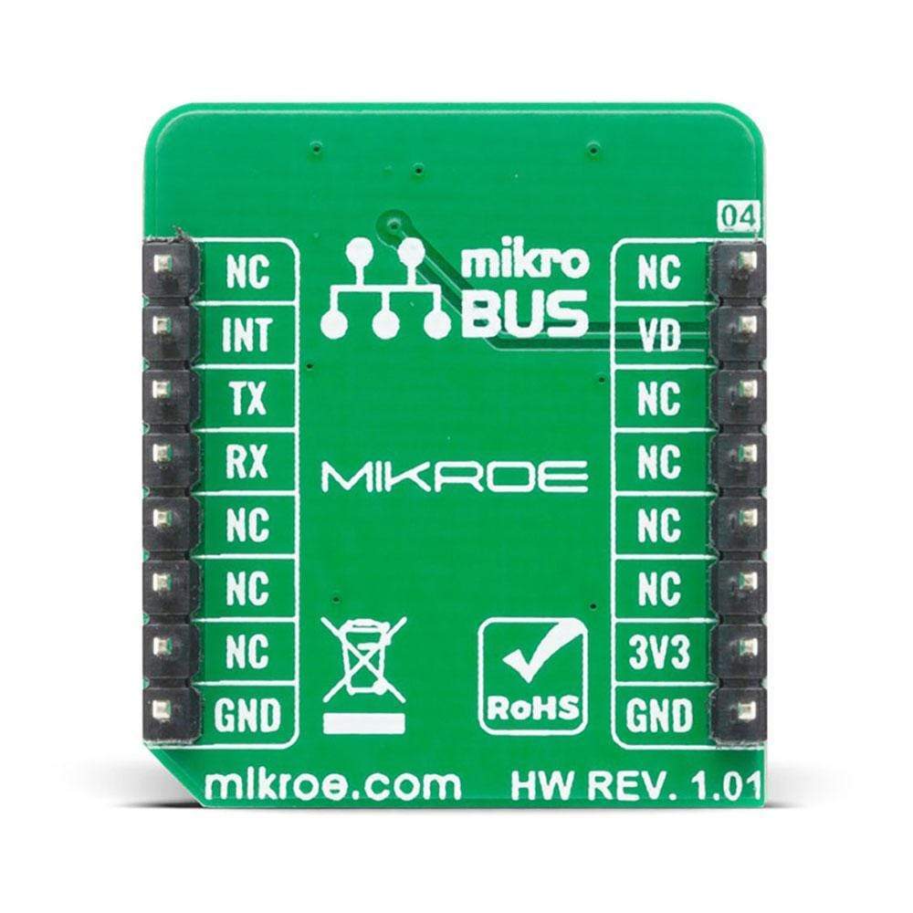
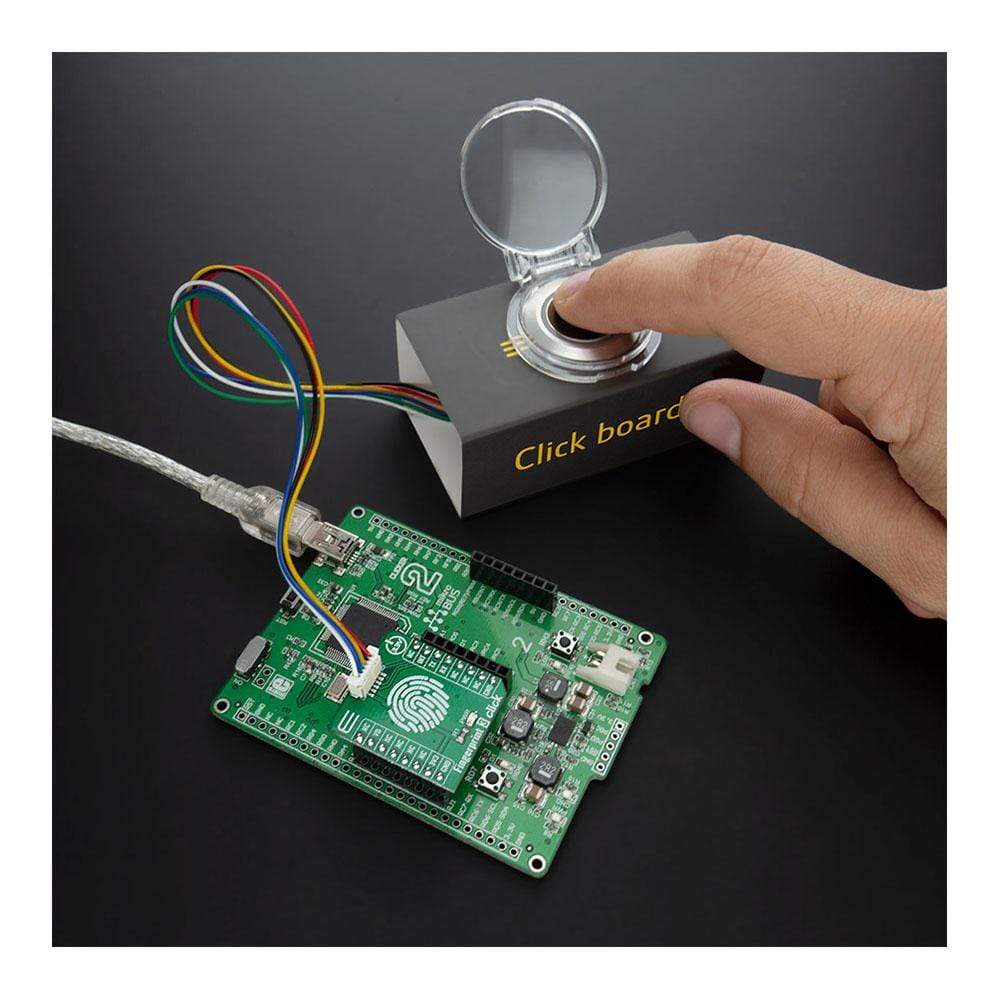
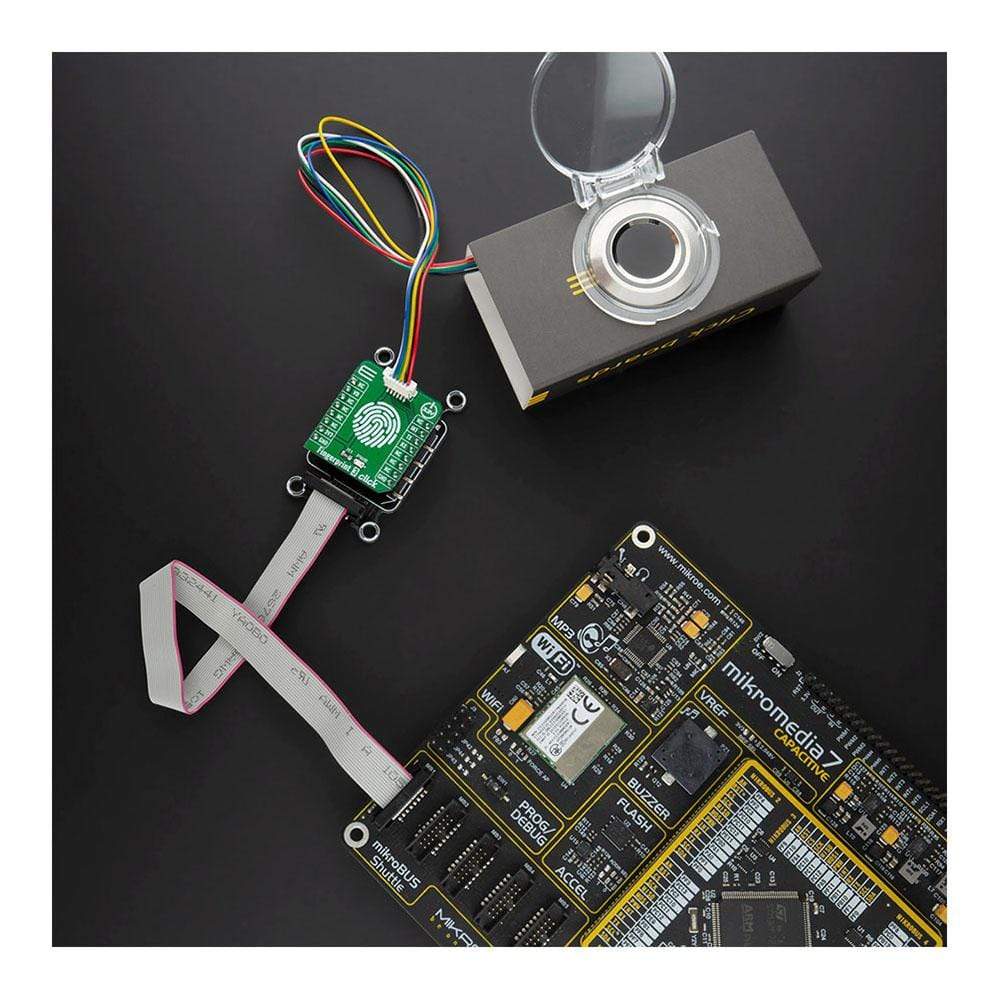
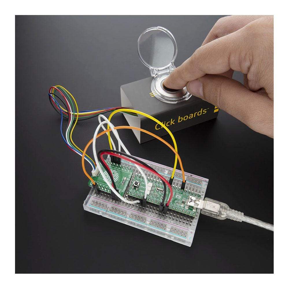
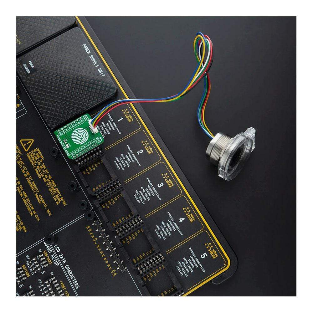
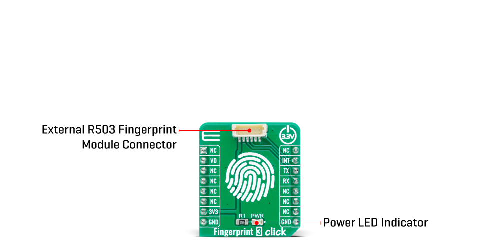
The Fingerprint 3 Click Board™ simplifies the connection of add-on boards to the mikroBUS™ socket. This Click board™ represents a small-size PCB that can be connected to the mikroBUS™ socket like any other Click board™, with a 1x6 1.0mm pitch vertical type wire to board connector placed on itself. Each of the header pins is corresponding to a pin on the mikroBUS™ socket being used such as UART lines (TX, RX), 3V3 power supply, finger detection signal and Ring LED enable for GROW R503 module, and ground. This Click board™ allows easy pin access and manipulation while retaining a perfect connection quality at all times.
Fingerprint processing includes two parts: fingerprint recording and fingerprint matching. The first step is the initialization of all the necessary drivers, peripherals, and pins. At power-on, it takes about 200ms for initialization, and during this period the module can't accept any commands. This is followed by checking the sensor and verifying the module password, after which, if everything is done correctly, the creation of a new fingerprint pattern begins. The user needs to enter the finger two times. The system will process the two-time finger images, generate a template of the finger based on processing results, and store the template. When matching, a user enters the finger through an optical sensor, and the system will generate a template of the finger and compare it with templates of the finger library. In both circumstances, the system will return the matching result, success, or failure. This can also be seen in an example code that contains easy to use functions that may be used as a reference for further development.
The Fingerprint 3 Click Board™ communicates with MCU using the UART interface with the default baud rate of 57600bps for the data transfer, while the GPIO pins on this Click board™ are used for finger detection and ring indicator LED enable. Ring indicator LED light labeled as VD can be enabled by toggling the signal routed to the RST pin on the mikroBUS™, while the signal routed to the INT pin on the mikroBUS™ represents an interrupt and indicates detection of a finger on the module. When the indicator glow with purple color, that means the module is in its Stand-By mode and waits for a finger to be pressed. In addition to purple, the module can also glow blue or red, which indicates the correctness of the fingerprint match (blue indicates that a pair is found, while red indicates that a pair was not found).
This Click board™ is designed to be operated only with a 3.3V logic voltage level. A proper logic voltage level conversion should be performed before the Click board™ is used with MCUs with different logic levels. However, the Click board™ comes equipped with a library that contains easy to use functions and an example code that can be used as a reference for further development.
SPECIFICATIONS
| Type | Adapter,Fingerprint |
| Applications | The Fingerprint 3 Click Board™ is adapter with socket for the capacitive fingerprint sensor module scanner with a two-color ring indicator. |
| On-board modules | The Fingerprint 3 Click Board™ is adapter with socket for the capacitive fingerprint sensor module scanner with a two-color ring indicator. |
| Key Features | Integrated image collecting, ring indicator, dust resistant, high recognition rate and the flexibility to adapt on different conditions of human finger, and more. |
| Interface | UART |
| Compatibility | mikroBUS |
| Click board size | S (28.6 x 25.4 mm) |
| Input Voltage | 3.3V |
PINOUT DIAGRAM
This table shows how the pinout on the Fingerprint 3 Click Board™ corresponds to the pinout on the mikroBUS™ socket (the latter shown in the two middle columns).
| Notes | Pin | Pin | Notes | ||||
|---|---|---|---|---|---|---|---|
| NC | 1 | AN | PWM | 16 | NC | ||
| Ring Indicator LED Enable | VD | 2 | RST | INT | 15 | INT | Fingerprint Detection |
| NC | 3 | CS | RX | 14 | RX | UART RX | |
| NC | 4 | SCK | TX | 13 | TX | UART TX | |
| NC | 5 | MISO | SCL | 12 | NC | ||
| NC | 6 | MOSI | SDA | 11 | NC | ||
| Power Supply | 3.3V | 7 | 3.3V | 5V | 10 | NC | |
| Ground | GND | 8 | GND | GND | 9 | GND | Ground |
ONBOARD SETTINGS AND INDICATORS
| Label | Name | Default | Description |
|---|---|---|---|
| LD1 | PWR | - | Power LED Indicator |
| General Information | |
|---|---|
Part Number (SKU) |
MIKROE-4265
|
Manufacturer |
|
| Physical and Mechanical | |
Weight |
0.016 kg
|
| Other | |
EAN |
8606027380501
|
Frequently Asked Questions
Have a Question?
Be the first to ask a question about this.