


Mikroelektronika d.o.o.
Angle Click Board™
Angle Click Board™
SKU: MIKROE-2030
Couldn't load pickup availability


Overview
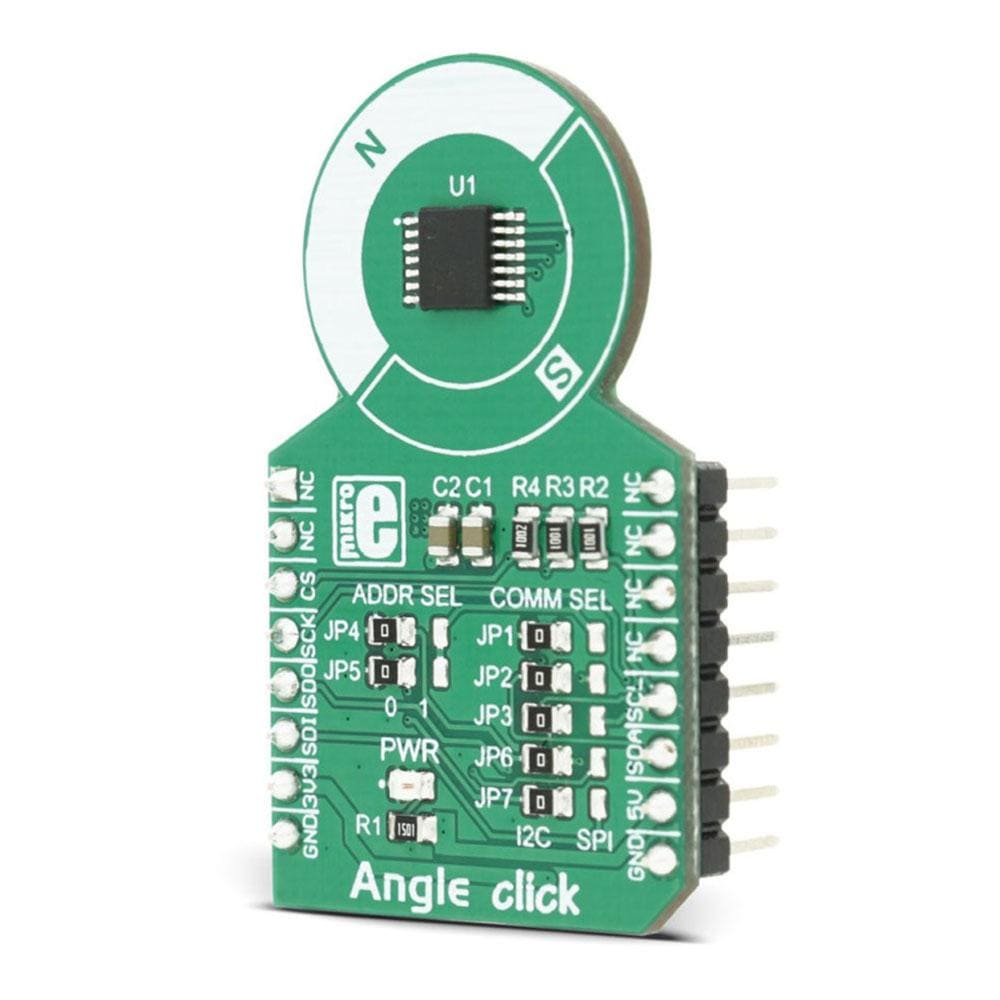
The Angle Click Board™ is a precise Hall-effect angle sensing click board that can be used to measure the rotational angle of the magnetic field in the X-Y plane above it (parallel to the surface of the click), through the whole range of 360°. The click yields very precise results for both off-axis and axis operation, which make it a perfect choice for precise measuring of the rotational angle in a wide range of different high-speed applications, for example in the automotive industry: electronic power steering, transmission, torsion bar, or the motor shaft rotation.
The Angle Click Board™ features the A1335 Hall-effect angle sensing IC, made by Allegro MicroSystems LLC. This IC measures the magnetic field angular vector, based on the actual physical reading of the integrated Hall-effect sensor, as well as the user-selected parameters, such as the digital filtering, dynamic range and scaling. The integrated 32-bit MCU ensures that the processed data is delivered with a minimal delay and it has enough power to provide the complex processing of the input values so that the measurement remains fast, precise and linear.
Downloads
The Angle Click Board™ is a precise Hall-effect angle sensing click board that can be used to measure the rotational angle of the magnetic field in the X-Y plane above it (parallel to the surface of the click), through the whole range of 360°. The click yields very precise results for both off-axis and axis operation, which make it a perfect choice for precise measuring of the rotational angle in a wide range of different high-speed applications, for example in the automotive industry: electronic power steering, transmission, torsion bar, or the motor shaft rotation.
The Angle Click Board™ features the A1335 Hall-effect angle sensing IC, made by Allegro MicroSystems LLC. This IC measures the magnetic field angular vector, based on the actual physical reading of the integrated Hall-effect sensor, as well as the user selected parameters, such as the digital filtering, dynamic range and scaling. The integrated 32bit MCU ensures that the processed data is delivered with a minimal delay and it has enough power to provide the complex processing of the input values so that the measurement remains fast, precise and linear.
How Does The Angle Click Board™ Work?
The Angle Click Board™ carries the A1335 Hall-effect angle sensing IC, which is actually a SoC architecture type of integrated circuit. It features a Circular Vertical Hall (CVH) technology, a high-speed sampling AD converter, MCU for the data processing and the section used for the I2C/SPI communication. Besides the SRAM registers which can be accessed by the I2C or the SPI, the IC features an EEPROM memory, used to permanently store configuration data. The device comes pre-programmed with the factory default register values, so it can properly operate in most cases. The detailed instructions on how to program the EEPROM memory can be found in the A1335 programming manual.
The rotation of the magnetic field is detected by the CVH sensor. This sensor detects the magnetic field presence by utilizing the effect the magnetic fields produces to the electron flow within the sensor, while the current flows through it - the Hall effect. The signal from the sensor is then digitized by the AD converter and handed to the digital front end of the IC. The digitalized signal is preconditioned, processed through the bandpass filter and the raw value of the angle is calculated. The value is then forwarded to the MCU unit. It is submitted to various steps of processing, depending on the register values set by the user. The more processing is done by the MCU, the less responsive the reading will be. MCU can perform several types of resource-demanding processing. Some of the algorithms that can be applied to the raw signal are:
- Angle averaging - the data is collected and averaged, depending on the selected output rate.
- IIR Filtering - the multi ordered filter can be applied to the raw values, with the selectable coefficient
- Gain Offset and Gain Adjust - allows setting the gain adjusting for a better resolution and zeroing out the raw rotation value.
- Angle Clamping - useful when rotation is less than 360°, this will limit the output values to the clamping ones.
- Harmonic Linearization - used to apply a user-defined error correction to the angle value.
These are just some of the options that can be set. The A1335 datasheet contains a detailed description for all of these functions. The required settings can be set via the registers and then used for the optimal measurement profile. The click can use either SPI or I2C for the communication. This can be set by the SMD jumpers. More about jumpers setting can be found in the Onboard settings and indicators table, below.
SPECIFICATIONS
| Type | Magnetic |
| Applications | Electronic power steering, torsion bar, digital potentiometer, and other applications requiring high speed 360º angle measurement |
| On-board modules | A1335 contactless magnetic angle position sensor |
| Key Features | 360º contactless high-resolution angle position sensor. Onboard EEPROM for storing calibration data. 32 microseconds refresh rate. Works both in on-axis and off-axis applications |
| Interface | SPI,I2C |
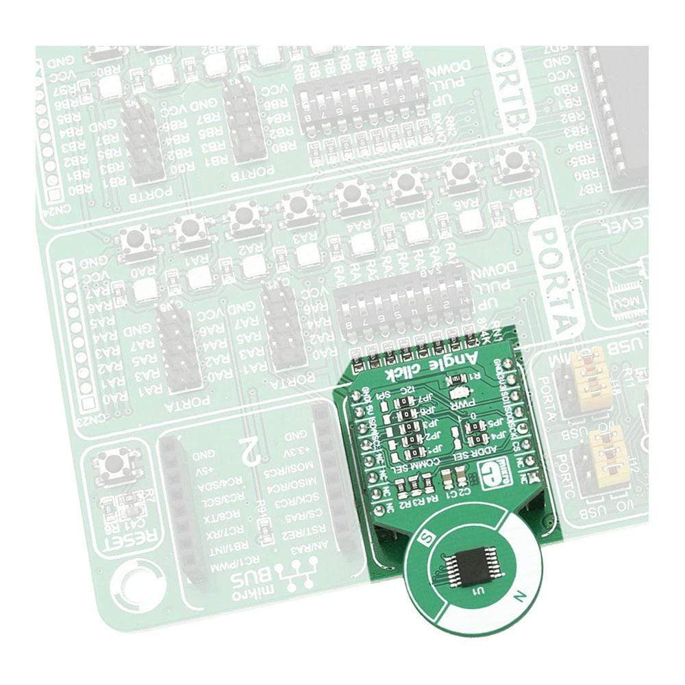
| Compatibility | mikroBUS |
| Click board size | M (42.9 x 25.4 mm) |
| Input Voltage | 5V,3.3V |
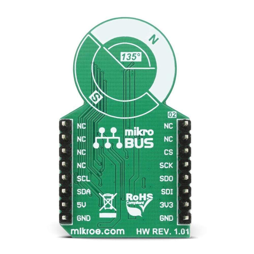
PINOUT DIAGRAM
This table shows how the pinout on the Angle Click Board™ corresponds to the pinout on the mikroBUS™ socket (the latter shown in the two middle columns).
| Notes | Pin | Pin | Notes | ||||
|---|---|---|---|---|---|---|---|
| NC | 1 | AN | PWM | 16 | NC | ||
| NC | 2 | RST | INT | 15 | NC | ||
| Chip Select | CS | 3 | CS | TX | 14 | NC | |
| SPI Clock | SCK | 4 | SCK | RX | 13 | NC | |
| SPI Data Output | SDO | 5 | MISO | SCL | 12 | SCL | I2C Clock |
| SPI Data Input | SDI | 6 | MOSI | SDA | 11 | SDA | I2C Data |
| Power Supply | +3V3 | 7 | 3.3V | 5V | 10 | +5V | Power Supply |
| Ground | GND | 8 | GND | GND | 9 | GND | Ground |
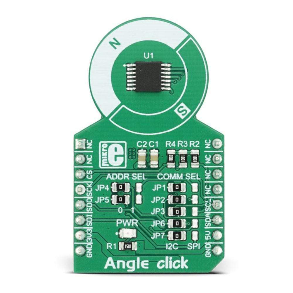
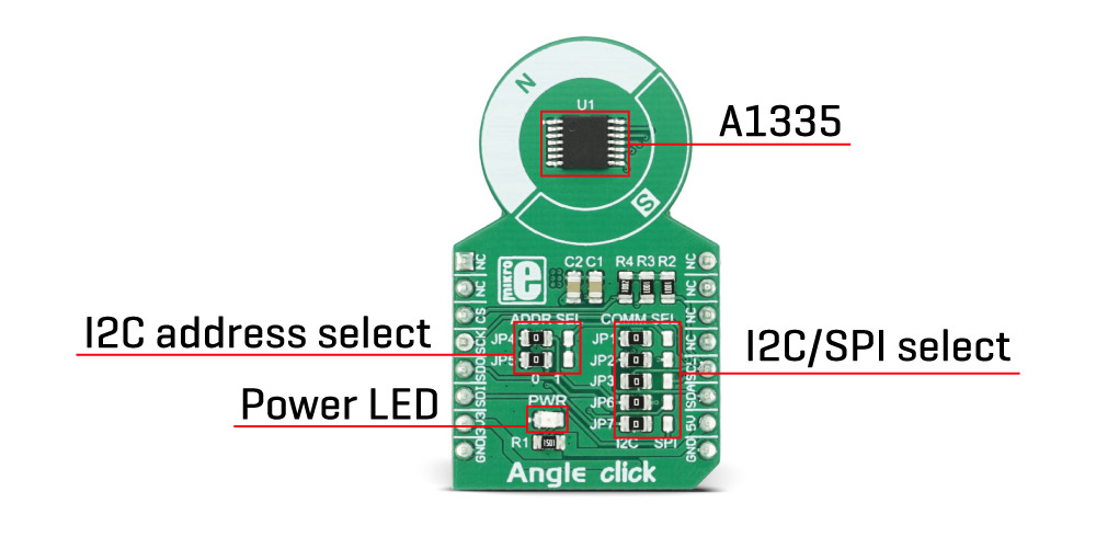
ONBOARD SETTINGS AND INDICATORS
| Label | Name | Default | Description |
|---|---|---|---|
| LD1 | PWR | - |
Power LED indicator, green
|
| JP1 | COMM SEL | Left | I2C/SPI selection: left position I2C, right position SPI |
| JP2 | COMM SEL | Left | SDA/MISO selection: left position SDA, right position MISO |
| JP3 | COMM SEL | Left | SCL/SCK selection: left position SCL, right position SCK |
| JP4 | ADDR SEL | Left | I2C Slave Address Select bit 0: left position '0', right position '1' |
| JP5 | ADDR SEL | Left | I2C Slave Address Select bit 1: left position '0', right position '1' |
| JP6 | COMM SEL | Left | SA0/CS selection: left position SA0, right position CS |
| JP7 | COMM SEL | Left | SA1/MOSI selection: left position SA1, right position MOSI |
Note: The Angle Click Board™ is set to I2C by default, with the Slave Address Selection bits (ADDR SEL) set to '0'. To select the SPI, all the COMM SEL jumpers have to be set to the right position. The ADDR SEL bits are disregarded in that case.
| General Information | |
|---|---|
Part Number (SKU) |
MIKROE-2030
|
Manufacturer |
|
| Physical and Mechanical | |
Weight |
0.018 kg
|
| Other | |
EAN |
8606015077383
|
Frequently Asked Questions
Have a Question?
Be the first to ask a question about this.