


Mikroelektronika d.o.o.
Accel 5 Click Board™
Accel 5 Click Board™
SKU: MIKROE-3149
Couldn't load pickup availability


Overview
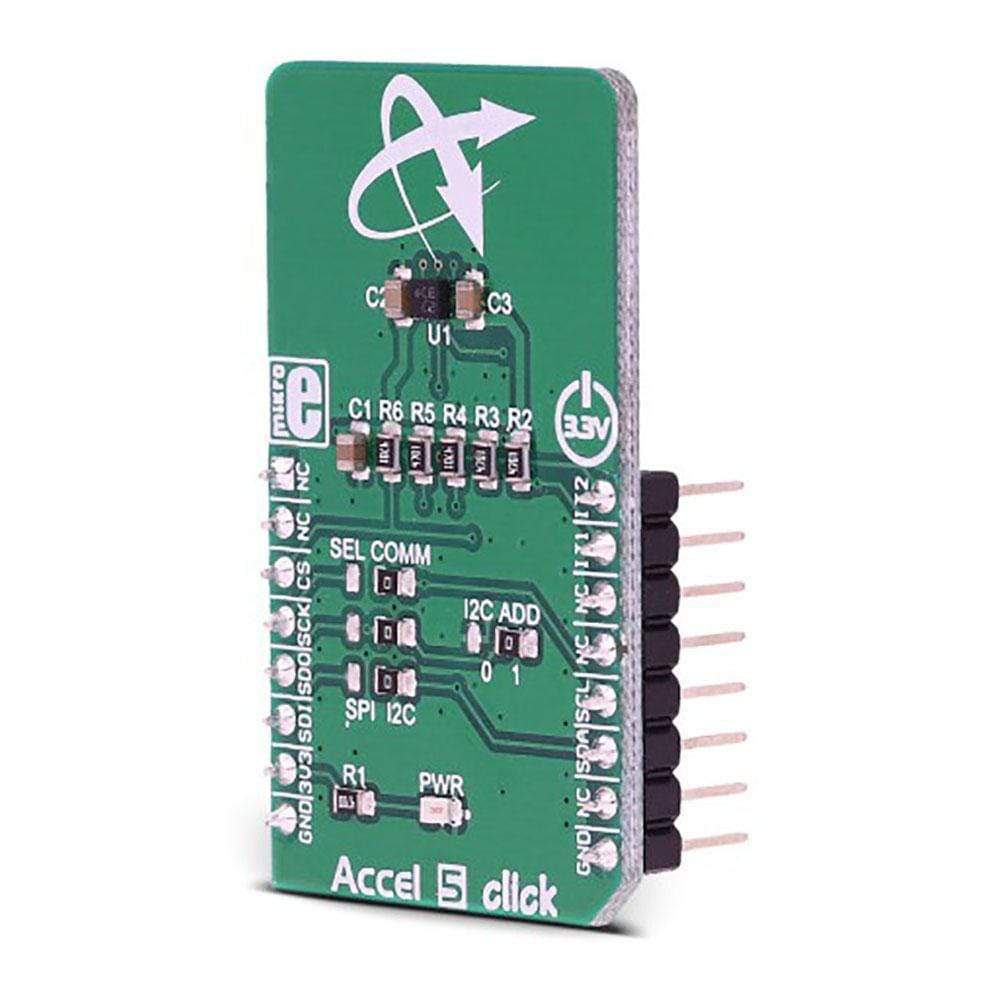
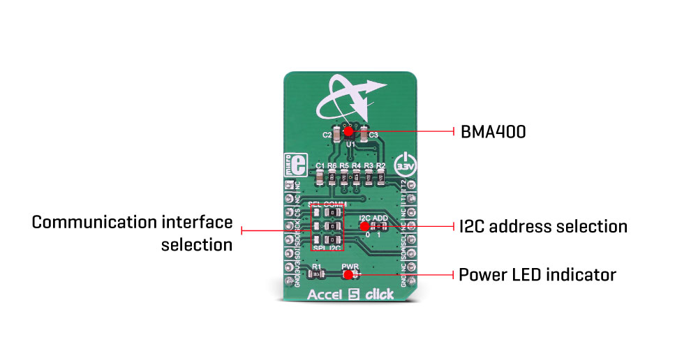
The Accel 5 Click Board™ features an ultra-low power triaxial accelerometer sensor, labelled as the BMA400. This Click Board™ allows linear motion and gravitational force measurements in ranges of ±2g, ±4g, ±8g, and ±16g in three perpendicular axes. Besides the acceleration measurement, the Accel 5 Click Board™ is able to output an interrupt for many different events, including tap, double-tap, step counting, activity recognition (walk, run, stand still), activity change (any type of acceleration pattern change), orientation, and more.
It features onboard data processing, offering the acceleration data directly, over the standard I2C or SPI interface. However, a key feature of the BMA400 sensor is its extremely low power consumption.
Downloads
With its ultra-low power consumption, onboard data processing, output data lowpass filtering, and ability to detect many different events, the Accel 5 click is a perfect solution for IoT applications. It can also be used to develop applications for wearables, where the BMA400 sensor shows its true potential, offering an ultra-low power always-on operation with no functionality compromises. In general, Accel 5 click can be used wherever a reliable detection of the acceleration-related events is needed: smart home applications, IoT applications, drop detection for warranty logging, power management based on motion, and similar.
How Does The Accel 5 Click Board™ Work?
The Accel 5 Click Board™ is based around the BMA400, an ultra-low power triaxial accelerometer sensor, from Bosch Sensortech. This sensor has many features perfectly suited for IoT applications and wearables, offering a good balance between the performance and the power consumption. One of its key features is its ultra-low power consumption, allowing it to be used in various always-on low power applications. To improve the battery life even more, this sensor also features a Sleep mode when the sensor current consumption is in magnitude of few hundred nanoamperes.
This sensor can measure the acceleration in ranges of ±2 g, ±4 g, ±8, and ±16 g. It also offers lowpass filtering of the output data, in the range from 0.48 x ODR (Output Data Refresh rate), up to maximal ODR frequency of 800Hz. An internal 12bit A/D converter ensures reliable and low noise operation, so that the data coming from the internal MEMS remains clean and accurate. Three power modes allow customized balance between the power consumption and performance. An extensive integrated interrupt engine offers many distinctive functionalities, such as the automatic enter/exit Low Power mode, advanced actions detection such as the running, walking, several other features such as the step counting…
After the POR (Power ON Reset) event, the device stays in the Sleep mode. In Sleep mode, the sensor practically does not consume any power (about 300nA), but the sensor functionality is completely suspended. To use the sensor, it has to be either in Low Power mode, where it uses a fixed Output Data Refresh (ODR) of 25Hz, or in the Normal mode. Some options are exclusive only to Normal mode, such as the step counting detection, output filtering and so on. Normal mode still uses power conservative, allowing the device to be used in the Always-ON low power applications.
While operating in Normal mode, two filters are available for the data filtering. The filters can be applied either to the output registers, the FIFO engine, or can be used to process the interrupt data. The first filter can be used to obtain data rates from 12.5Hz up to 800Hz, which is defined by the filter registers, while the second filter offers fixed frequency of 100Hz, superimposed by a frequency of 1Hz. The output noise is affected by the ODR frequency.
Acceleration data is available in 12-bit format from both the data registers and the internal FIFO buffer of 1kb. The FIFO buffer can be used for more complex calculations or timed readings. Writing to FIFO buffer is only allowed in the Normal mode, while it can be read in the Low power mode, too. The interrupt engine facilitates the complete FIFO buffer, triggering an interrupt for several FIFO events: overflow event, watermark event, almost full event, and so on.
The BMA400 sensor contains an integrated timer, which can be used along with the interrupts to be used for the auto Wakeup or auto Power down functions. The automatic functions are a part of the sensor power management. The automatic mode changes can be set either to an acceleration interrupt after a specified threshold is reached, or it can be set to a timer interrupt: when the timer expires, the interrupt is generated, and the power mode is switched.
An extensive interrupt engine offers two layers of interrupts. It offers basic interrupts, including some basic functions, such as the Data Ready interrupt, FIFO buffer related interrupts and the Wakeup event interrupt. Basic interrupts also report Interrupt overrun event, where too many interrupts are competing, so that the sensor is not able to process them all.
Besides the basic interrupts, the interrupt engine offers some more sophisticated, advanced interrupts, that include detection all of the activities: tap/double tap, step counting, activity changed, orientation changed, and two generic interrupts. The advanced interrupts require a certain ODR rate and can be used in the Normal mode exclusively, while basic interrupts offer more rudimental control over events.
The advanced interrupt engine can use two programmable interrupt pins. Both of these pins can be assigned with any interrupt source and can be either LOW or HIGH on interrupt, depending on settings in appropriate registers. These two pins are routed to INT and PWM pins of the mikroBUS™, and are labeled as IT1 and IT2, respectively.Besides the acceleration MEMS and complementary analog front-end circuitry, the BMA400 sensor also has an integrated temperature sensor. It is updated every 160ms and sampled with the 8-bit resolution. Thermal data is always available, except when the device is in the Sleep mode.
The Accel 5 Click Board™ offers two communication interfaces. It can be used with either I2C or SPI. The onboard SMD jumpers labeled as SEL COM allow switching between the two interfaces. Note that all the jumpers have to be positioned either to I2C or to SPI position. When I2C interface is selected, an additional SMD jumper labeled as the I2C ADD becomes available, determining the least significant bit of the BMA400 I2C address. The Click board™ should be interfaced only with MCUs that operate on 3.3V
SPECIFICATIONS
| Type | Acceleration,Motion |
| Applications | It can be used for display orientation, HID applications, drop detection applications (for warranty logging), pedometer, step counter, and similar applications that rely on reliable acceleration and motion-sensing. |
| On-board modules | BMA400, a 12bit triaxial acceleration sensor with ultra-low power consumption, from Bosch Sensortec |
| Key Features | Advanced interrupt engine allows detection of various events, ultra-low power consumption allows using in always-on IoT and wearable applications, auto wakeup / auto low power mode based on the interrupt event, thermal readings also available |
| Interface | I2C,SPI |
| Compatibility | mikroBUS |
| Click board size | M (42.9 x 25.4 mm) |
| Input Voltage | 3.3V |
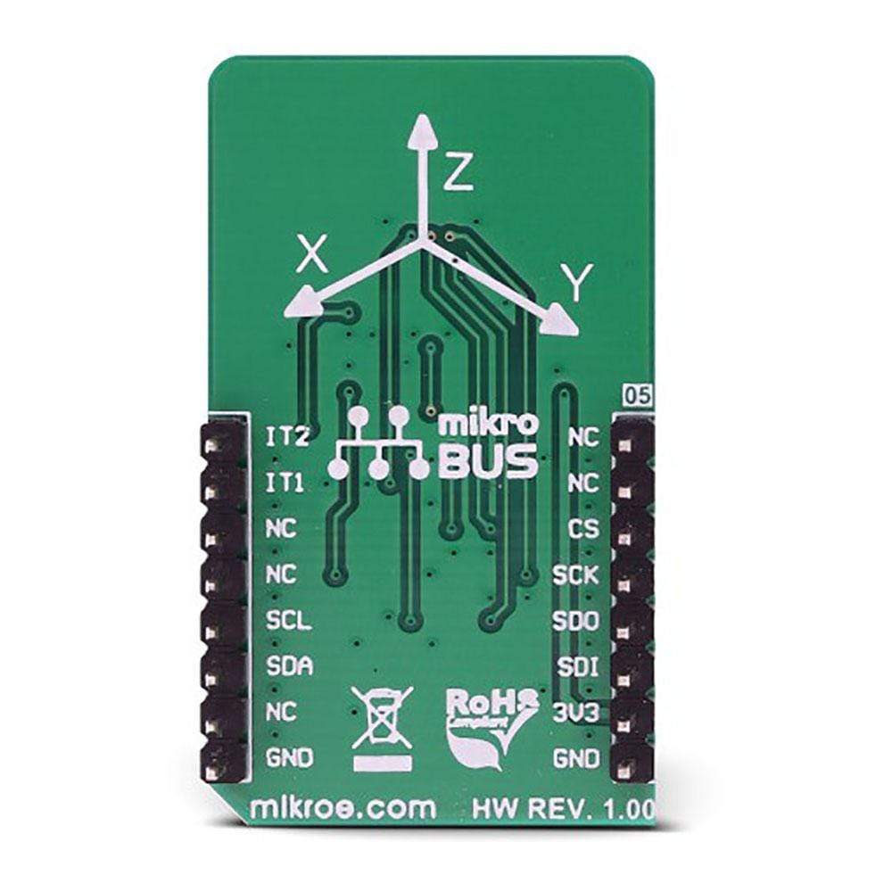
PINOUT DIAGRAM
This table shows how the pinout on the Accel 5 Click Board™ corresponds to the pinout on the mikroBUS™ socket (the latter shown in the two middle columns).
| Notes | Pin | Pin | Notes | ||||
|---|---|---|---|---|---|---|---|
| NC | 1 | AN | PWM | 16 | IT2 | INT OUT 2 | |
| NC | 2 | RST | INT | 15 | IT1 | INT OUT 1 | |
| SPI Chip Select | CS | 3 | CS | RX | 14 | NC | |
| SPI Clock | SCK | 4 | SCK | TX | 13 | NC | |
| SPI Data OUT | SDO | 5 | MISO | SCL | 12 | SCL | I2C Clock |
| SPI Data IN | SDI | 6 | MOSI | SDA | 11 | SDA | I2C Data |
| Power supply | 3.3V | 7 | 3.3V | 5V | 10 | NC | |
| Ground | GND | 8 | GND | GND | 9 | GND | Ground |
ACCEL 5 CLICK ELECTRICAL SPECIFICATIONS
| Description | Min | Typ | Max | Unit |
|---|---|---|---|---|
| Acceleration measurement range | ±2 | - | ±16 | g |
| Output refresh rate | 12.5 | - | 800 | Hz |
| Thermal measurement range | -40 | - | +87.5 | ˚C |
ONBOARD SETTINGS AND INDICATORS
| Label | Name | Default | Description |
|---|---|---|---|
| LD1 | PWR | Power LED indicator | |
| JP1-JP3 | COM SEL | Left | Communication interface selection: left position I2C, right position SPI |
| JP4 | I2C ADD | Right | I2C address LSB selection: left position 0, right position 1 |
| General Information | |
|---|---|
Part Number (SKU) |
MIKROE-3149
|
Manufacturer |
|
| Physical and Mechanical | |
Weight |
0.019 kg
|
| Other | |
EAN |
8606018713523
|
Frequently Asked Questions
Have a Question?
Be the first to ask a question about this.