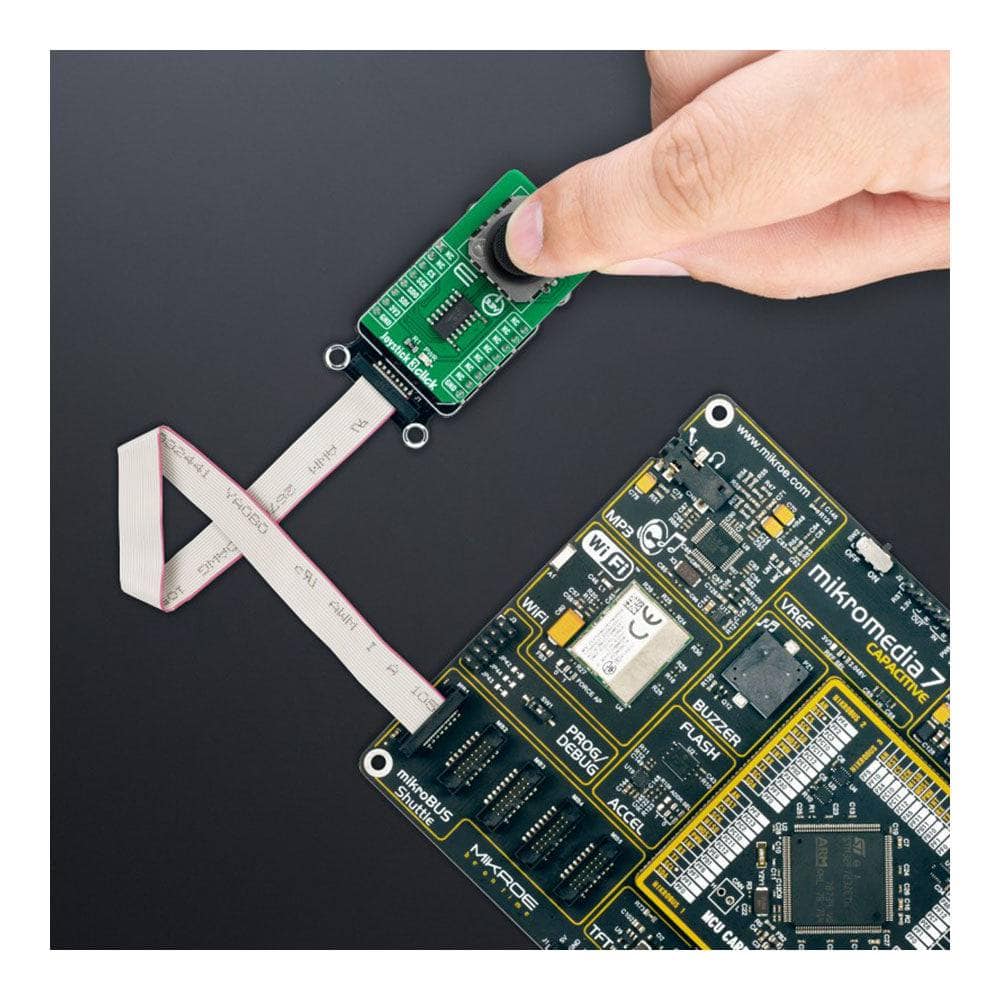
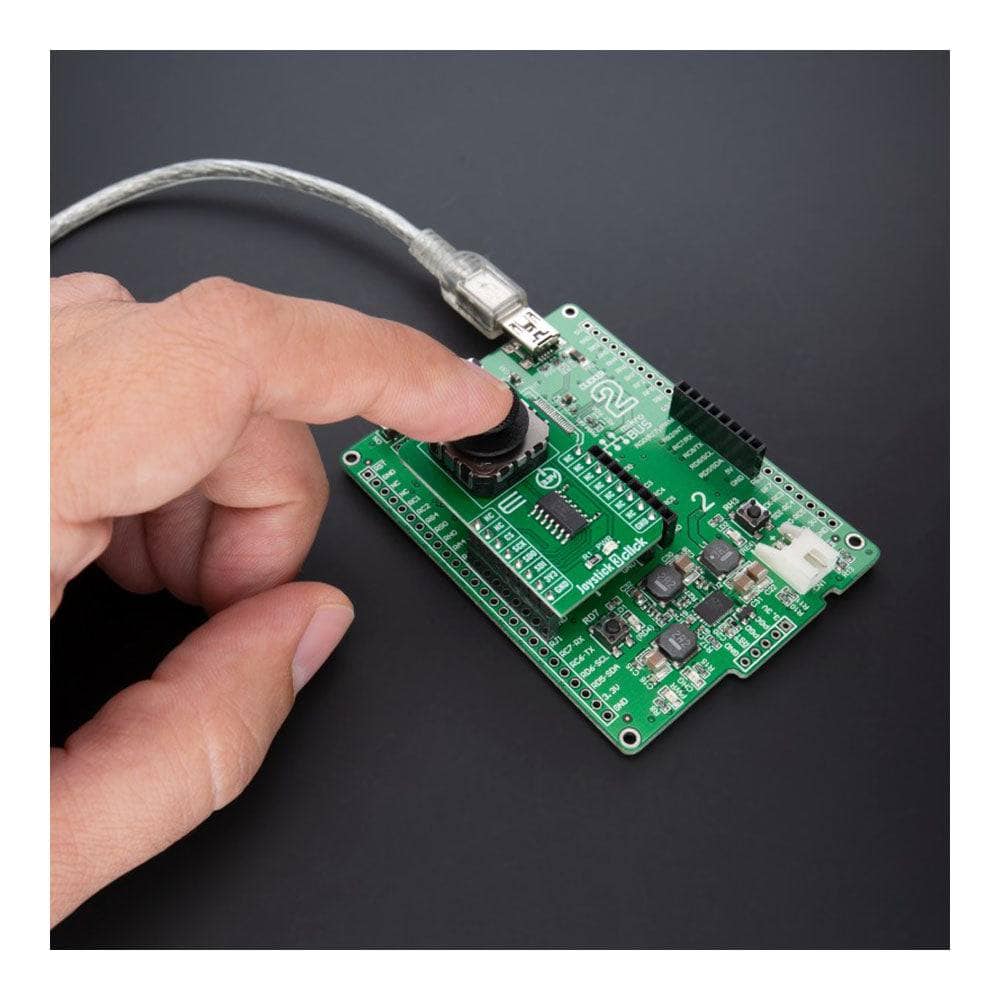
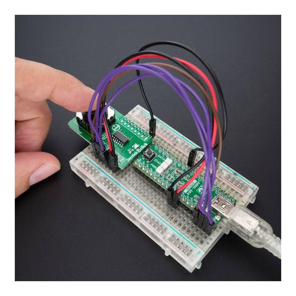
Joystick 3 Click Board
Key Features
- Low power consumption, high quality, high mechanical and electrical durability, self-centring feature, 2-axis, SPI interface, and more
- Based on the 2765 - mini 2-axis analogue-type thumbstick from Adafruit Industries
- Can be used for numerous applications as a human-machine interface device (HMI), robotics, and other control interfaces
- mikroBUS: SPI Interface
Experience precise directional control with Joystick 3 Click Board™
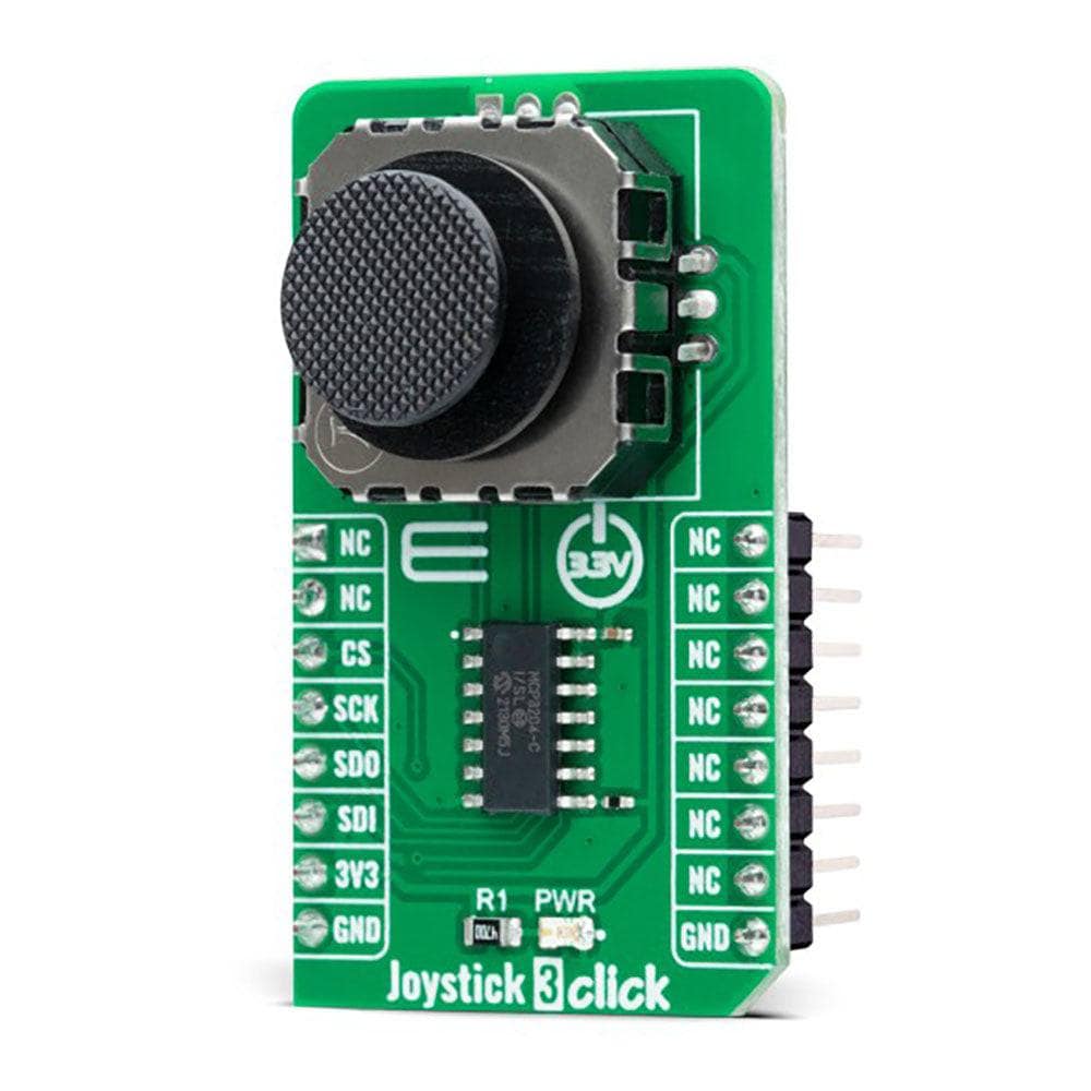
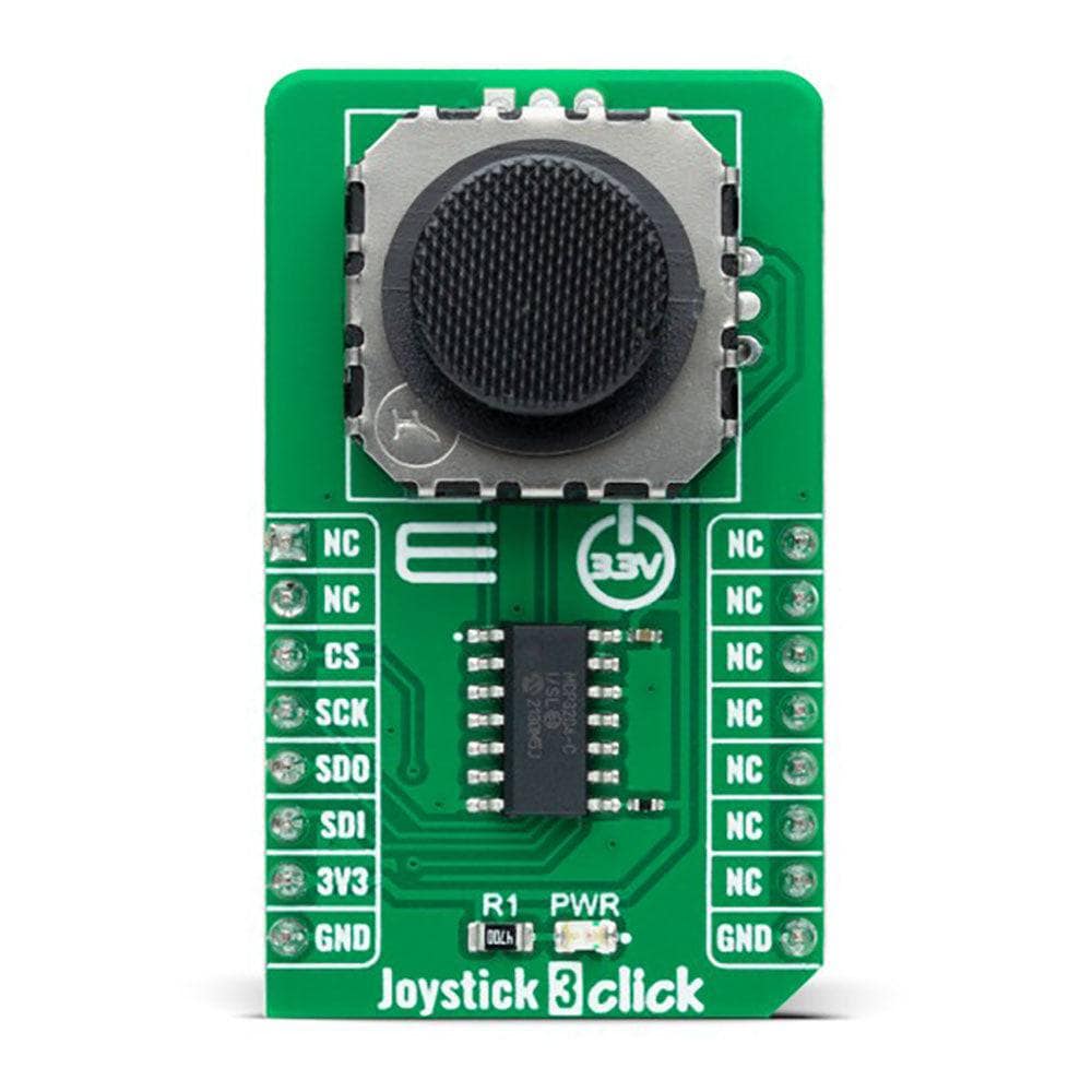
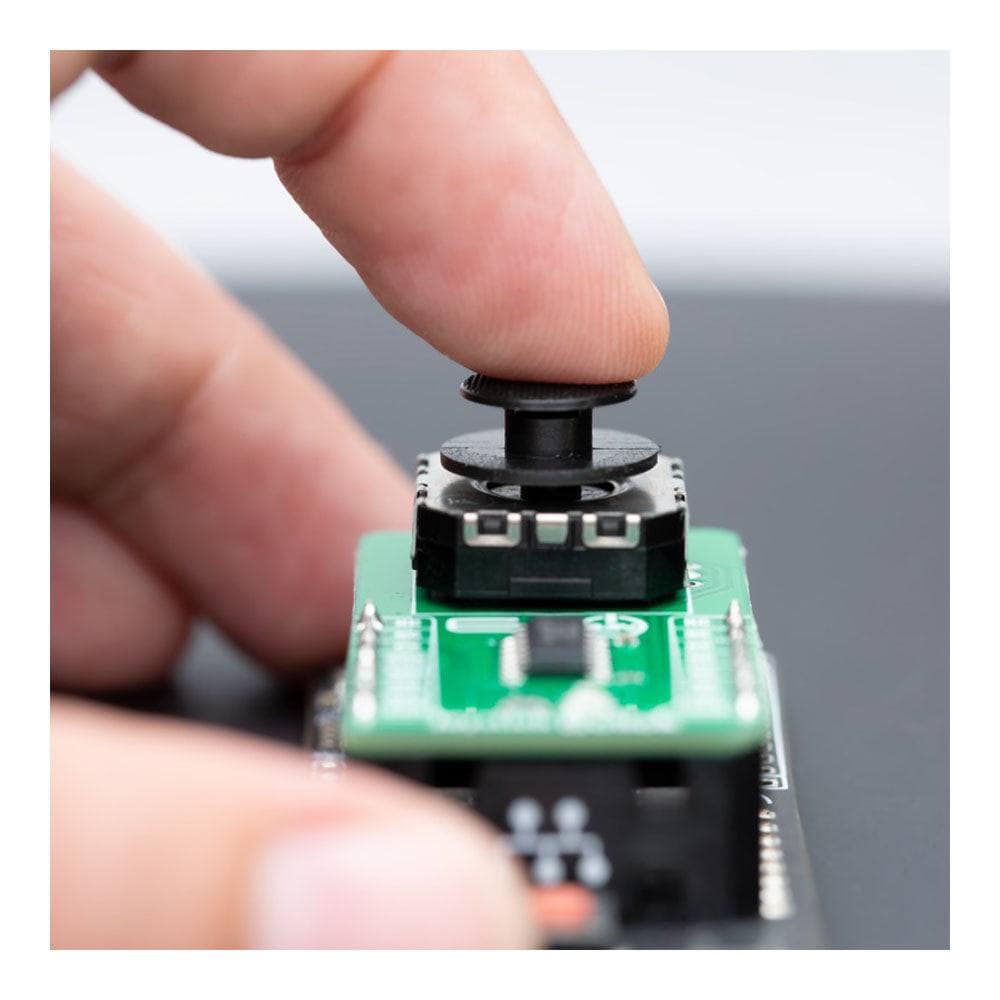
Upgrade your directional analogue input needs with the compact and high-quality Joystick 3 Click Board™. This add-on board features the 2765 mini 2-axis analogue output thumbstick from Adafruit Industries, providing you with a 'self-centring' analogue-type joystick with a black rocker cap similar to PSP joysticks.
Precise control with 10kΩ potentiometers
The Joystick 3 Click Board™ is equipped with two 10kΩ potentiometers, one for up/down and another for left/right direction. These potentiometers ensure accurate and precise control, making this Click board™ perfect for various applications such as human-machine interface devices (HMI), robotics, and other control interfaces.
Seamless connection with mikroBUS™
The Joystick 3 Click Board™ connects seamlessly with mikroBUS™ through the MCP3204 12-bit A/D converter. This ensures fast and efficient data transfer, providing you with smooth and responsive control.
Simplified software development with mikroSDK-compliant library
Developing software for the Joystick 3 Click Board™ is a breeze with the mikroSDK-compliant library. This library includes functions that simplify software development, making it easier for you to get started with your project.
Ready-to-use, thoroughly tested product
The Joystick 3 Click Board™ comes as a thoroughly tested product, ensuring that it's ready to be used on a system equipped with the mikroBUS™ socket. This means that you can start using the Click board™ right out of the box, without any additional setup or testing required.
Upgrade your control interfaces and HMI devices with the Joystick 3 Click Board™ today!
How Does The Joystick 3 Click Board™ Work?
The Joystick 3 Click Board™ is based on the 2765, a high-quality mini 2-axis analogue-type thumbstick from Adafruit Industries. This type of joystick has a self-centring feature that allows it to centre itself the moment when you release the joystick. It also contains a comfortable cup-type black knob/cap, which gives the feel of a thumbstick, making it very similar to the 'analogue' joysticks on PSP joysticks, suitable for numerous applications as a human-machine interface.
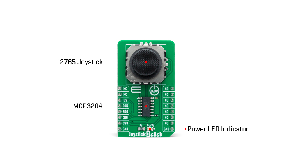
The Joystick 3 Click Board™ comprises two 10kΩ potentiometers, one for up/down and another for left/right direction, used as dual adjustable voltage dividers providing 2-axis analogue input in a control stick form. With the joystick fully assembled and functioning, the voltage will follow the motion of the thumbstick as it is moved around.
The measurements of the potentiometer resistance change are needed to read the joystick's physical position. That's why the MCP3204, a 12-bit A/D converter from Microchip, connects the joystick with mikroBUS™ using a simple serial interface compatible with the SPI protocol to determine the value of the joystick's X and Y. As the MCP3204 has a resolution of 12 bits, the values on each analogue channel (axis) can vary from 0 to 4095. So, if the stick is moved on the X axis from one end to the other, the X values will change from 0 to 4095, and a similar thing happens when moved along the Y axis. The value of the joystick staying in its centre position is around 2048. Also, the MCP3204 is capable of conversion rates of up to 100ksps.
The Joystick 3 Click Board™ can be operated only with a 3.3V logic voltage level. The board must perform appropriate logic voltage level conversion before using MCUs with different logic levels. However, the Click board™ comes equipped with a library containing functions and an example code that can be used, as a reference, for further development.
SPECIFICATIONS
Type | Pushbutton/Switches |
Applications | The Joystick 3 Click Board™ be used for numerous applications as a human-machine interface device (HMI), robotics, and other control interfaces |
On-board modules | 2765 - mini 2-axis analogue-type thumbstick from Adafruit Industries |
Key Features | Low power consumption, high quality, high mechanical and electrical durability, self-centring feature, 2-axis, SPI interface, and more |
Interface | SPI |
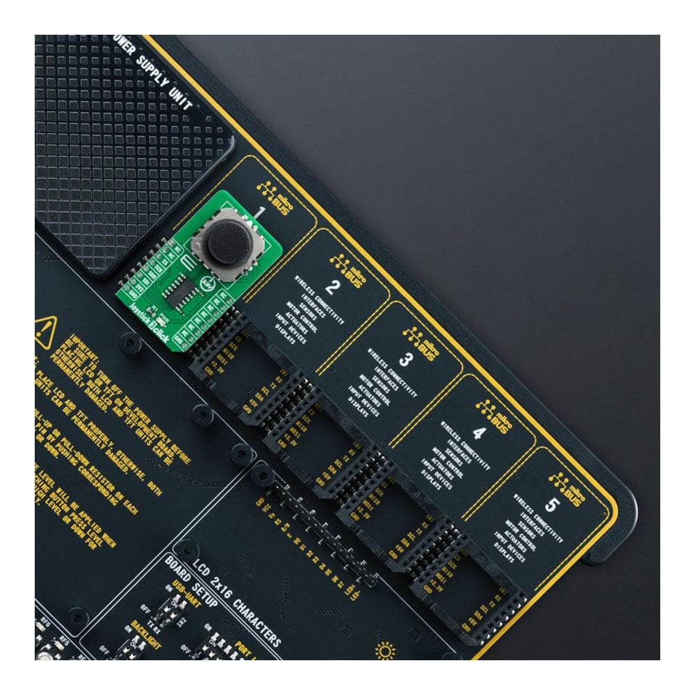
Compatibility | mikroBUS |
Click board size | M (42.9 x 25.4 mm) |
Input Voltage | 3.3V |
PINOUT DIAGRAM
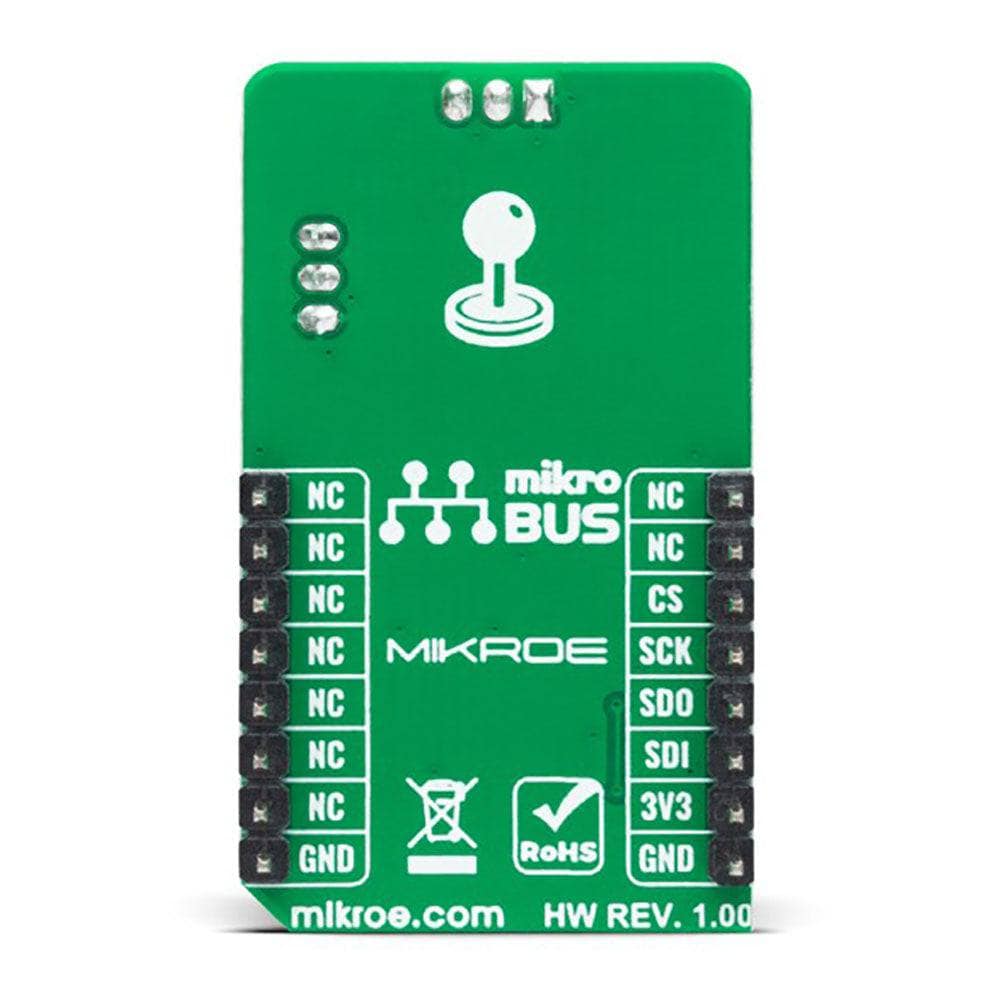
This table shows how the pinout of the Joystick 3 Click Board™ corresponds to the pinout on the mikroBUS™ socket (the latter shown in the two middle columns).
Notes | Pin | Pin | Notes | ||||
---|---|---|---|---|---|---|---|
NC | 1 | AN | PWM | 16 | NC | ||
NC | 2 | RST | INT | 15 | NC | ||
SPI Chip Select | CS | 3 | CS | RX | 14 | NC | |
SPI Clock | SCK | 4 | SCK | TX | 13 | NC | |
SPI Data OUT | SDO | 5 | MISO | SCL | 12 | NC | |
SPI Data IN | SDI | 6 | MOSI | SDA | 11 | NC | |
Power Supply | 3.3V | 7 | 3.3V | 5V | 10 | NC | |
Ground | GND | 8 | GND | GND | 9 | GND | Ground |
ONBOARD SETTINGS AND INDICATORS
Label | Name | Default | Description |
---|---|---|---|
LD1 | PWR | - | Power LED Indicator |
JOYSTICK 3 CLICK ELECTRICAL SPECIFICATIONS
Description | Min | Typ | Max | Unit |
---|---|---|---|---|
Supply Voltage | - | 3.3 | - | V |
2765 Potentiometer Resistance | - | 10 | - | kΩ |
ADC Resolution | - | 12 | - | bits |
Operating Temperature Range | 0 | +25 | +80 | °C |
Software Support
We provide a library for the Joystick 3 Click Board™ as well as a demo application (example), developed using MikroElektronika compilers. The demo can run on all the main MikroElektronika development boards.
The package can be downloaded/installed directly from NECTO Studio The package Manager (recommended), downloaded from our LibStock™ or found on the MikroE Github account.
Library Description
This library contains API for the Joystick 3 Click Board™ driver.
Key functions
-
joystick3_read_raw_adc
This function reads the raw ADC for X and Y axis by using SPI serial interface. -
joystick3_get_angle
This function calculates and returns the joystick angle in degrees from raw ADC values for X and Y axis. -
joystick3_get_position
This function calculates and returns the joystick position flag from raw ADC values for X and Y axis.
Example Description
This example demonstrates the use of the Joystick 3 Click Board™ by reading and displaying the raw ADC for the X and Y axis, as well as the joystick angle and position calculated from those ADC readings.
void application_task ( void )
{
uint16_t raw_x, raw_y;
if ( JOYSTICK3_OK == joystick3_read_raw_adc ( &joystick3, &raw_x, &raw_y ) )
{
log_printf ( &logger, " RAW X: %urn RAW Y: %urn", raw_x, raw_y );
log_printf ( &logger, " Joystick angle: %.1f degreesrn", joystick3_get_angle ( raw_x, raw_y ) );
log_printf ( &logger, " Joystick position: " );
switch ( joystick3_get_position ( raw_x, raw_y ) )
{
case JOYSTICK3_POSITION_NEUTRAL:
{
log_printf ( &logger, "NEUTRAL" );
break;
}
case JOYSTICK3_POSITION_UP:
{
log_printf ( &logger, "UP" );
break;
}
case JOYSTICK3_POSITION_UPPER_RIGHT:
{
log_printf ( &logger, "UPPER-RIGHT" );
break;
}
case JOYSTICK3_POSITION_RIGHT:
{
log_printf ( &logger, "RIGHT" );
break;
}
case JOYSTICK3_POSITION_LOWER_RIGHT:
{
log_printf ( &logger, "LOWER-RIGHT" );
break;
}
case JOYSTICK3_POSITION_DOWN:
{
log_printf ( &logger, "DOWN" );
break;
}
case JOYSTICK3_POSITION_LOWER_LEFT:
{
log_printf ( &logger, "LOWER-LEFT" );
break;
}
case JOYSTICK3_POSITION_LEFT:
{
log_printf ( &logger, "LEFT" );
break;
}
case JOYSTICK3_POSITION_UPPER_LEFT:
{
log_printf ( &logger, "UPPER-LEFT" );
break;
}
default:
{
log_printf ( &logger, "UNKNOWN" );
break;
}
}
log_printf ( &logger, "rnn" );
Delay_ms ( 100 );
}
}
The complete application code and ready-to-use projects can be installed directly from NECTO Studio. The package Manager (recommended) is downloaded from our LibStock™ or found on the MikroE Github account.
Other MikroE Libraries used in the example:
- MikroSDK.Board
- MikroSDK.Log
- Click.Joystick3
Additional Notes and Information
Depending on the development board you are using, you may need USB UART Click Board™, USB UART 2 Click, or RS232 Click to connect to your PC for development systems with no UART to USB interface available on the board. UART terminal is available in all MikroElektronika compilers.
MIKROSDK
The Joystick 3 Click Board™ is supported with mikroSDK - MikroElektronika Software Development Kit. To ensure proper operation of mikroSDK compliant Click board™ demo applications, mikroSDK should be downloaded from the LibStock and installed for the compiler you are using.
Joystick 3 Click Board
Frequently Asked Questions
Have a Question?
Be the first to ask a question about this.