


Mikroelektronika d.o.o.
BATT-MAN 3 Click Board™
BATT-MAN 3 Click Board™
SKU: MIKROE-4909
Couldn't load pickup availability


Overview
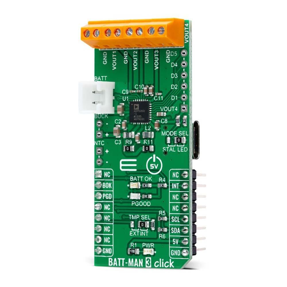
The BATT-MAN 3 Click Board™ is a compact add-on board representing an advanced battery management solution. This board features the ADP5350, a power management IC with inductive boost LED, and three LDO regulators from Analog Devices. This I2C programmable board supports USB optimized for USB voltage input. It combines one high-performance buck regulator for single Li-Ion/Li-Ion polymer battery charging, a fuel gauge, a highly programmable boost regulator for LED backlight illumination, and three 150mA LDO regulators.
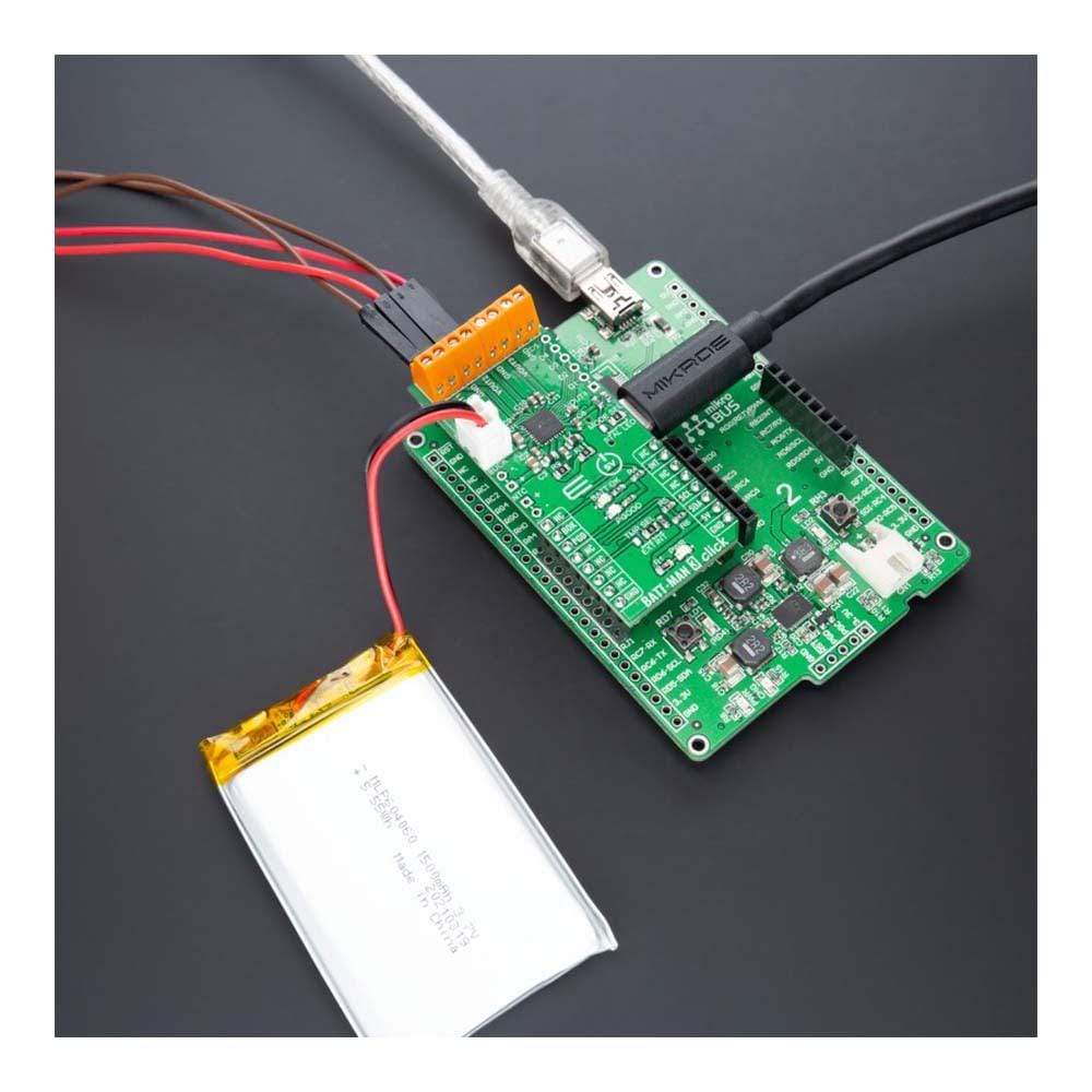
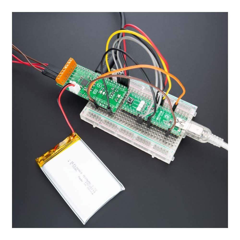
The BATT-MAN 3 Click Board™ is suitable for rechargeable Li-Ion and Li-Ion Polymer battery-powered devices, portable customer and instrumentation devices, and many more.
Downloads
How Does The BATT-MAN 3 Click Board™ Work?
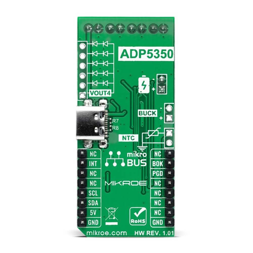
The BATT-MAN 3 Click Board™ as its foundation uses the ADP5350, an advanced battery management PMIC with inductive boost LED, and three LDO regulators from Analog Devices. It combines one high-performance buck regulator for single Li-ion/Li-ion polymer battery charging (also available on left side header labeled as BUCK), a fuel gauge, a highly programmable boost regulator for LED backlight illumination, one ultralow quiescent current low dropout (LDO) regulator, and two general-purpose LDO regulators. Besides, it supports a USB connection optimized for USB 5V input.
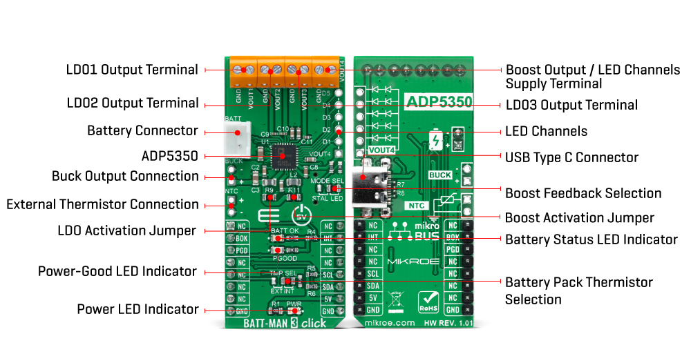
The ADP5350 operates in trickle charge mode and constant current (CC)/constant voltage (CV) fast charge mode. It also features an internal field-effect transistor (FET) that permits battery isolation on the system power side. The ADP5350 fuel gauge is a low current consuming solution optimal for rechargeable Li-Ion battery-powered devices. Its boost regulator operates at a 1.5MHz switching frequency and can be employed as a constant voltage regulator or supplemental constant current regulator for multiple LED backlight drivers available on the VOUT4 terminal.
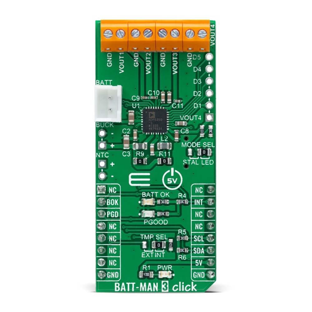
This LED driver can support a wide range of LED backlight configurations, either multiple LEDs in parallel or series connected on the upper-right onboard header. This Click board™ also has a feedback-sensing for the boost regulator, which can be selected for standalone mode or LED operation mode by positioning the SMD jumpers labeled as MODE SEL to an appropriate position marked as STAL and LED. An additional option has been added for the users to activate or deactivate the Boost and LED part of the board by populating or removing two jumpers, R11 and R9.
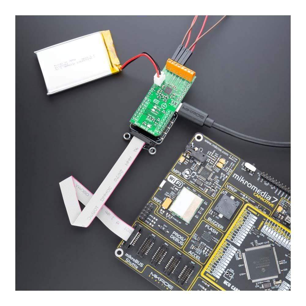
The BATT-MAN 3 Click Board™ communicates with MCU using the standard I2C 2-Wire interface to read data and configure settings with a maximum frequency of 400kHz. Also, it uses several GPIO pins, one of which is an interrupt pin, the INT pin of the mikroBUS™ socket, used as a 'fault' indicator which immediately notifies the host when a fault occurs. The ADP5350 low dropout (LDO) regulators, available on top side terminals labeled from VOUT1 to VOUT3, are optimized to operate at low shutdown current and quiescent current to extend battery life. The device also acts as a load switch that can be fully turned OFF or ON. The I2C interface enables the programmability of all parameters, including status bit readback for operation monitoring and safety control.
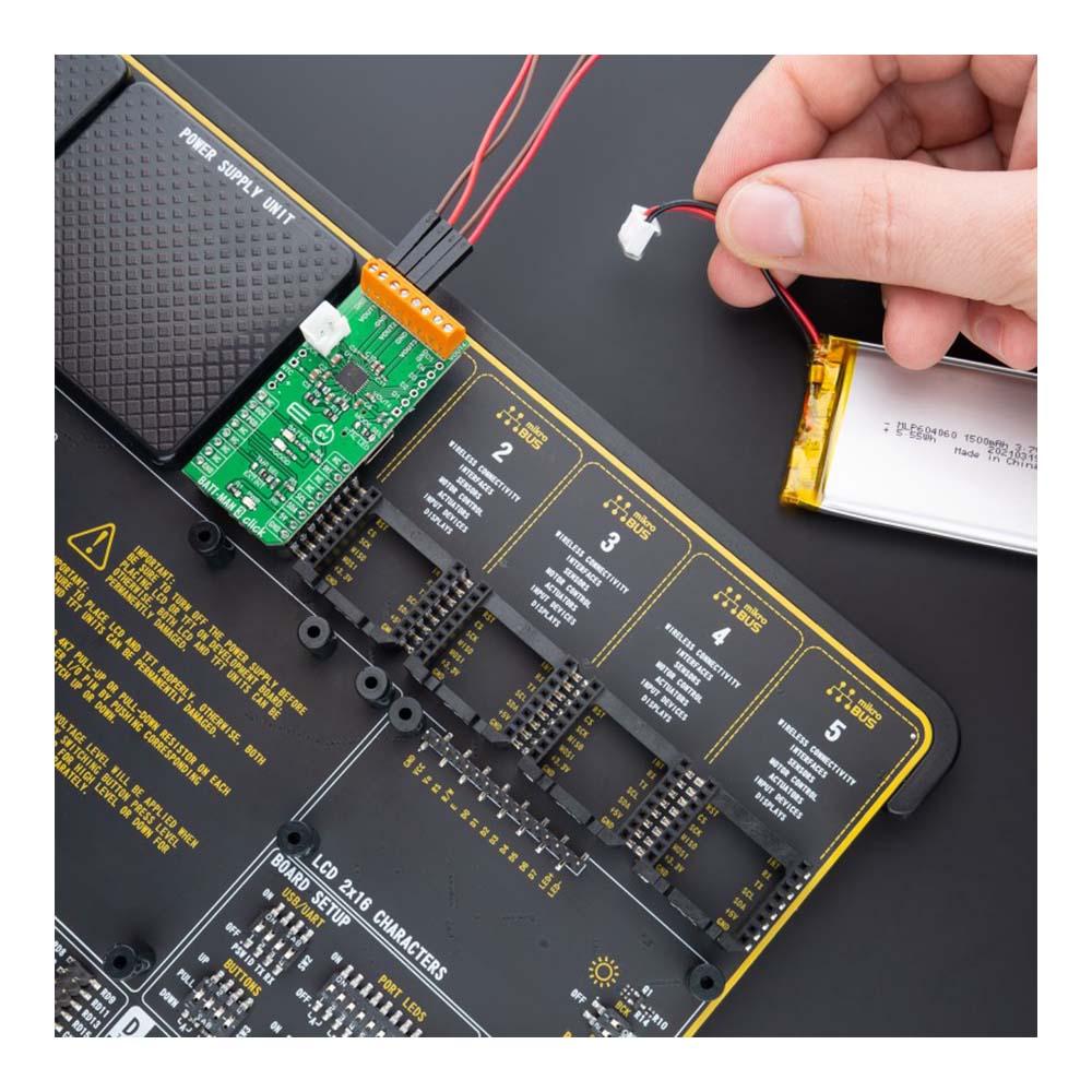
The BATT-MAN 3 Click Board™ uses two LED indicators, labeled as PGOOD and BATT OK, used as power good and charging status indicator alongside the connector on the upper-left side of the board, reserved for a Li-ion/Li-ion polymer battery. PGOOD indicates a good input source, while BATT OK shows the real-time status of the battery voltage. Also, it features battery pack temperature sensing via an internal or external thermistor connected to the onboard header labeled as NTC. This sensing precludes charging when the battery pack temperature is outside the specified range. The selection of a thermistor can be made by positioning the SMD jumpers labeled as TMP SEL to an appropriate position marked as EXT and INT.
The BATT-MAN 3 Click Board™ can be operated only with a 5V logic voltage level. The board must perform appropriate logic voltage level conversion before using MCUs with different logic levels. However, the Click board™ comes equipped with a library containing functions and an example code that can be used, as a reference, for further development.
SPECIFICATIONS
| Type | Buck-Boost |
| Applications | The BATT-MAN 3 Click Board™ be used for rechargeable Li-Ion and Li-Ion Polymer battery-powered devices, portable customer and instrumentation devices, and many more |
| On-board modules | ADP5350 - advanced battery management PMIC with inductive boost LED, and three LDO regulators from Analog Devices |
| Key Features | Switching mode USB battery charger, boost regulator with five-channel LED driver, three 150mA linear LDO regulators, full I2C programmability with dedicated interrupt pin, LED indicators, external NTC, and more |
| Interface | I2C |
| Compatibility | mikroBUS |
| Click board size | L (57.15 x 25.4 mm) |
| Input Voltage | 5V |
PINOUT DIAGRAM
This table shows how the pinout for the BATT-MAN 3 Click Board™ corresponds to the pinout on the mikroBUS™ socket (the latter shown in the two middle columns).
| Notes | Pin | Pin | Notes | ||||
|---|---|---|---|---|---|---|---|
| NC | 1 | AN | PWM | 16 | NC | ||
| Battery Status | BOK | 2 | RST | INT | 15 | INT | Interrupt |
| Power-Good Status | PGD | 3 | CS | RX | 14 | NC | |
| NC | 4 | SCK | TX | 13 | NC | ||
| NC | 5 | MISO | SCL | 12 | SCL | I2C Clock | |
| NC | 6 | MOSI | SDA | 11 | SDA | I2C Data | |
| NC | 7 | 3.3V | 5V | 10 | 5V | Power Supply | |
| Ground | GND | 8 | GND | GND | 9 | GND | Ground |
ONBOARD SETTINGS AND INDICATORS
| Label | Name | Default | Description |
|---|---|---|---|
| LD1 | PWR | - | Power LED Indicator |
| LD2 | BATT OK | - | Battery Status LED Indicator |
| LD3 | PGOOD | - | Power-Good LED Indicator |
| JP1 | TMP SEL | Right | Battery Pack Thermistor Selection EXT/INT: Left position EXT, Right position INT |
| JP2 | MODE SEL | Right | Boost Feedback Selection STAL/LED: Left position STAL, Right position LED |
| J1 | NTC | Unpopulated | External Thermistor Header |
| J2 | BUCK | Unpopulated | Buck Output Header |
| J1 | NTC | Unpopulated | External Thermistor Header |
| J4 | D1-D5 | Unpopulated | LED Channels Header |
| J4 | VOUT4 | Unpopulated | LED Channels Supply Voltage Header |
| R9 | R9 | Populated | LDO Activation Jumper |
| R11 | R11 | Populated | Boost Activation Jumper |
BATT-MAN 3 CLICK ELECTRICAL SPECIFICATIONS
| Description | Min | Typ | Max | Unit |
|---|---|---|---|---|
| Supply Voltage VCC | - | 5 | - | V |
| Programmable Current Limit | 100 | - | 1500 | mA |
| LDO Output Current | - | 150 | - | mA |
| LED Current | - | - | 20 | mA |
| Operating Temperature Range | -40 | +25 | +125 | °C |
| General Information | |
|---|---|
Part Number (SKU) |
MIKROE-4909
|
Manufacturer |
|
| Physical and Mechanical | |
Weight |
0.02 kg
|
| Other | |
EAN |
8606027389856
|
Frequently Asked Questions
Have a Question?
Be the first to ask a question about this.