BIG 7-SEG R Click Board
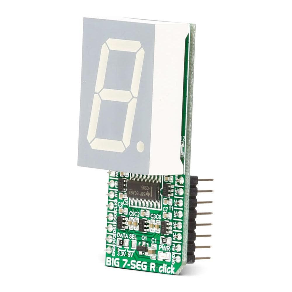
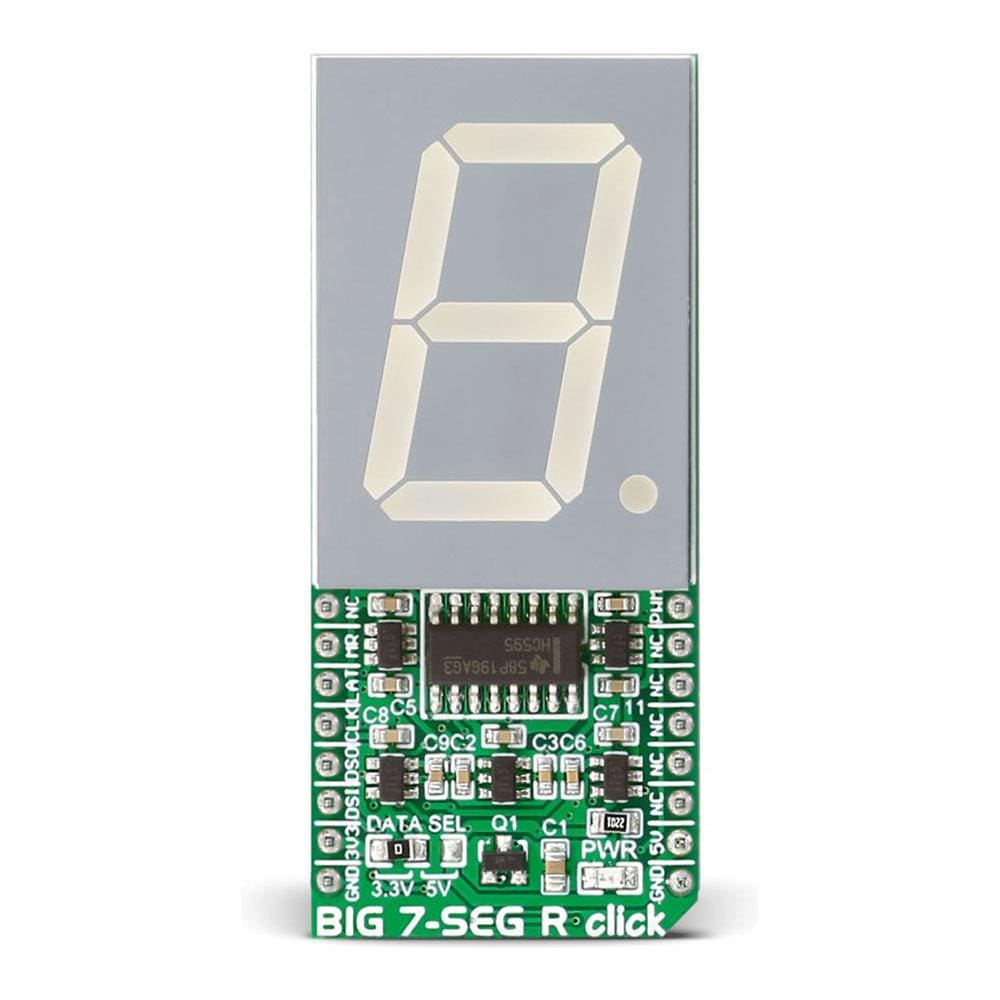
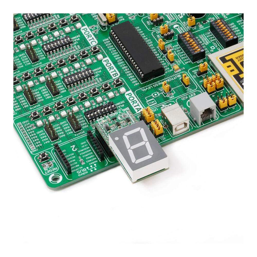
The BIG 7-Seg R Click Board™ is what you need if you want to add a seven-segment LED display to your project. This click features an SC10-21SRWA seven-segment display. Communication between the MCU and the SC10-21SRWA display is established via serial-IN, parallel-OUT shift register 74HC595 IC.
The BIG 7-Seg R Click Board™ runs on either 3.3V or 5V power supply and communicates with the target MCU over an SPI interface.
The BIG 7-Seg R Click Board™ is what you need if you want to add a seven-segment LED display to your project. This Click Board™ features an SC10-21SRWA seven-segment display. Communication between the MCU and the SC10-21SRWA display is established via serial-IN, parallel-OUT shift register 74HC595 IC.
The BIG 7-Seg R Click Board™ runs on either 3.3V of 5V power supply and communicates with the target MCU over an SPI interface.
Display
The BIG 7-Seg R Click Board™ displays letters, numbers and symbols in highly readable form. It can be used in any simple interface and combined with other Click Board™s. The color of the displayed character is red, as the R in the name of the Click Board™ states.
Light Intensity
The light intensity on the display is controlled via the PWM pin on the board.
Applications
Adding a seven-segment LED display to your device with SPI interface.
SPECIFICATIONS
Type | 7-segment,LED Segment |
Applications | Adding a seven-segment LED display to your device with SPI interface |
On-board modules | SC10-21SRWA seven-segment display, parallel-OUT shift register 74HC595 IC |
Key Features | 1.0 inch digit height, Standard: grey face, white segment, Low current operation |
Interface | GPIO,PWM,SPI |
Compatibility | mikroBUS |
Click board size | L (57.15 x 25.4 mm) |
Input Voltage | 3.3V or 5V |
PINOUT DIAGRAM
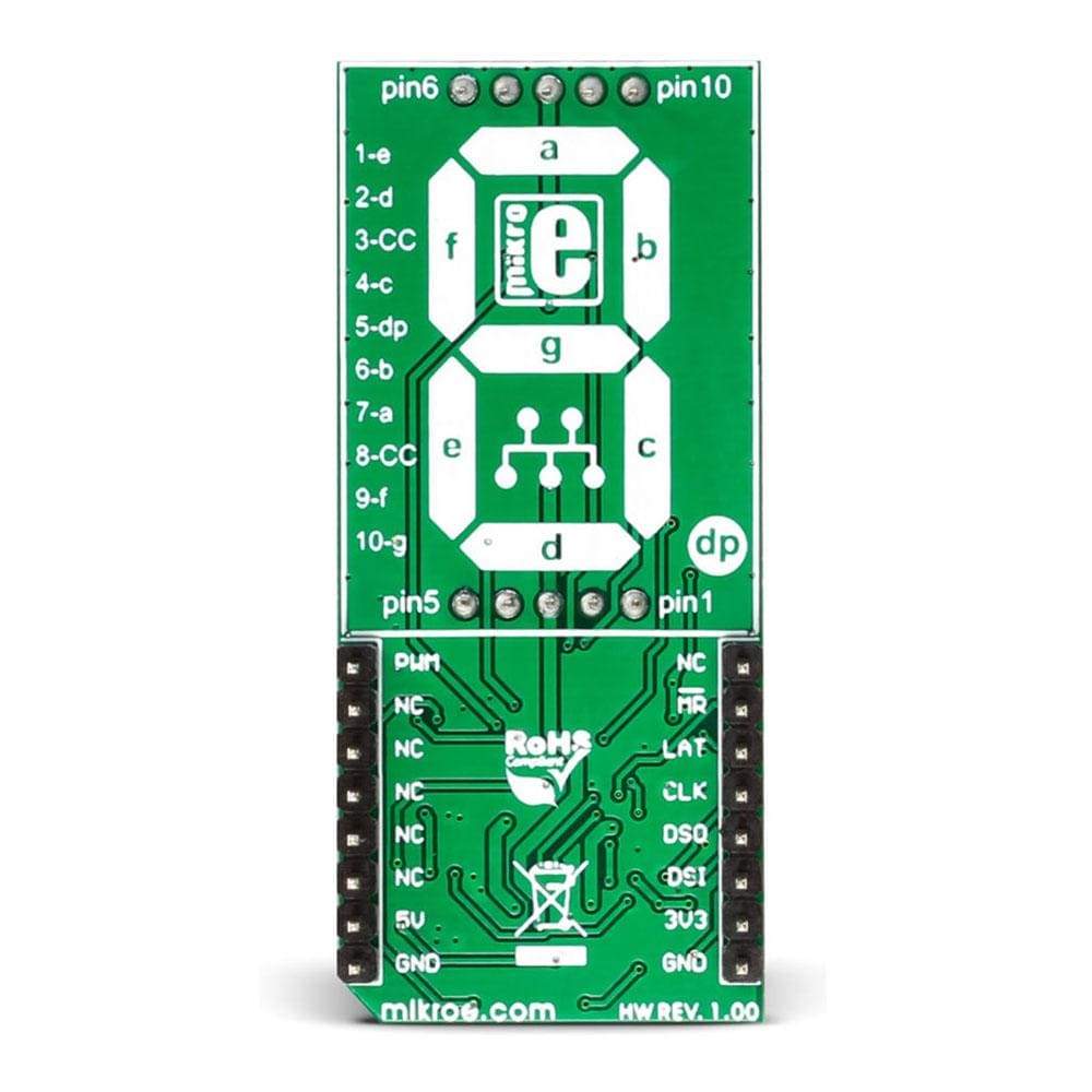
This table shows how the pinout on the BIG 7-Seg R Click Board™ corresponds to the pinout on the mikroBUS™ socket (the latter shown in the two middle columns).
Notes | Pin | Pin | Notes | ||||
---|---|---|---|---|---|---|---|
NC | 1 | AN | PWM | 16 | PWM | Display light intensity control | |
Master Reset for 74HC595 | MR | 2 | RST | INT | 15 | NC | |
Latch for 74HC595 | LAT | 3 | CS | TX | 14 | NC | |
Clock for 74HC595 | CLK | 4 | SCK | RX | 13 | NC | |
Serial Data from 74HC595 to MCU | DSO | 5 | MISO | SCL | 12 | NC | |
Serial Data from MCU to 74HC595 | DSI | 6 | MOSI | SDA | 11 | NC | |
Data line when interfaced with 3.3V MCU | 3.3V | 7 | +3.3V | +5V | 10 | 5V | Data line when interfaced with 5V MCU and also power supply pin for display and the whole click hardware |
Ground | GND | 8 | GND | GND | 9 | GND | Ground |
JUMPERS AND SETTINGS
Information about onboard jumpers:
Designator | Name | Default Position | Default Option | Description: describe the use + list all options with respective descriptions |
---|---|---|---|---|
JP1 | Logic level | Left | 3.3V | Logic Level Selection toward host mcu 3.3V/5V, left position 3.3V, right position 5V |
Software Support
This demo is using the BIG 7-Seg R Click Board™ to display characters in an endless loop, with fixed time interval whilst changing its PWM duty.
- Operating Voltage Range: 2.0 to 6.0 V
- Operating Temperature: – 55 to 125 C
This example for STM32F107VC MCU ( EasyMx PRO v7 for ARM ), resets and initializes the BIG 7-Seg R Click Board™ takes characters from the static array and displays them while changing PWM duty cycle, all in an endless loop.
1 extern char dig_array[MAX_CHARACTERS]; 2 3 // Variables 4 unsigned short counter; 5 unsigned int luminosity; 6 unsigned int pwm_period; 7 int8_t valid; 8 9 char demo_array[20] = 10 { 'M', 'I', 'K', 'R', 'O', 11 'E', 'L', 'E', 'K', 'T', 'R', 'O', 'N', 'I', 'K', 'A', 12 '2', '0', '1', '6' 13 }; 14 15 void main() 16 { 17 // MCU Init 18 GPIO_Digital_Output(&GPIOD_ODR, _GPIO_PINMASK_13); // Set PORTD.B13 as digital input 19 GPIO_Digital_Output(&GPIOC_ODR, _GPIO_PINMASK_2); // Set PORTC.B2 as digital output 20 21 // SPI Init 22 SPI3_Init_Advanced( _SPI_FPCLK_DIV16, _SPI_MASTER | _SPI_8_BIT | 23 _SPI_CLK_IDLE_LOW | _SPI_FIRST_CLK_EDGE_TRANSITION | 24 _SPI_MSB_FIRST | _SPI_SS_DISABLE | _SPI_SSM_ENABLE | 25 _SPI_SSI_1, &_GPIO_MODULE_SPI3_PC10_11_12 ); 26 27 // PWM Init 28 pwm_period = PWM_TIM5_Init(5000); // PWM Init on 5kHz 29 PWM_TIM5_Set_Duty(100, _PWM_NON_INVERTED, _PWM_CHANNEL1); 30 PWM_TIM5_Start(_PWM_CHANNEL1, &_GPIO_MODULE_TIM5_CH1_PA0); 31 32 // 74HC595 Init 33 HC595_LAT = 0; 34 HC595_RES = 0; 35 HC595_reset(); 36 37 // Init counter and segment luminosity 38 counter = 0; 39 luminosity = 0; 40 41 // Endless loop 42 while (1) 43 { 44 valid = seg_7_display(demo_array[counter]); 45 PWM_TIM5_Set_Duty(100 + luminosity, _PWM_NON_INVERTED, _PWM_CHANNEL1); 46 delay_ms(750); 47 luminosity += 100; 48 counter++; 49 if (counter == 20) 50 counter = 0; 51 if (luminosity == 4000) 52 luminosity = 0; 53 } 54 }
BIG 7-SEG R Click Board
Frequently Asked Questions
Have a Question?
Be the first to ask a question about this.