Comparator Click Board
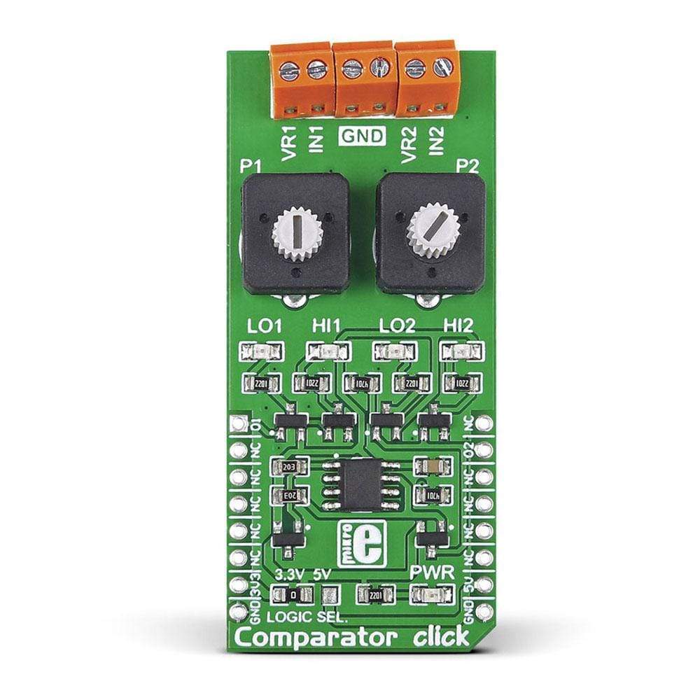
The Comparator Click Board™ from MikroElektronika is a voltage comparator on a Click Board™ add-on board carrying an LM2903 precision voltage comparators. This LM2903 IC features two independent voltage comparators, two pairs of screw terminals (additional two screw terminals are for GND connections), and two potentiometers.
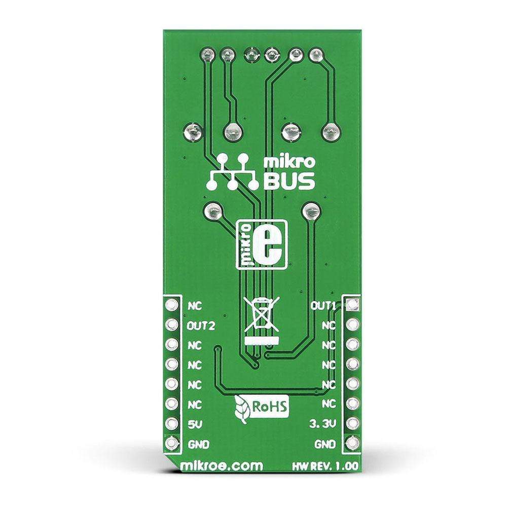
It can be used with either a single or dual power supply over a wide range of voltages. The screw terminals allow the user to connect separate inputs, while the two potentiometers, placed between the screw terminals and the IC, configure the setpoint voltage. Each input has its own interrupt pin on the socket, i.e., one through the MikroBUS INT pin, the other in place of the default MikroBUS AN pin.
The Comparator Click Board™ is designed to use either a 3.3V or a 5V power supply.
IC/module: LM2903 IC
The LM2903 IC consists of two independent precision voltage comparators on the Click Board™ that operate over an extensive range of voltages. The comparators can operate from a single power supply as well as dual supplies.
How Does The Comparator Click Board Work?
When paired with analog sensors, the Comparator Click Board™ allows user to hook up an analog signal. The voltage from this analog signal is used as an input and compared with the physical value set as a reference by using the potentiometer. The device will then digitally check if your input voltage is higher or lower than the referenced value. If the input value exceeds, an interrupt signal is triggered.
Power: Single-Supply or Dual Supplies
The Comparator Click Board™ is designed to be used with single or dual power supply. For single power supply,
Software Support
Library Description
The library covers all the necessary functions to control the Comparator Click Board™. The Comparator Click Board™ communicates with the device via GPIO driver. This library contains drivers for check state of the OUT1 and OUT2 pin function.
Key Functions
- uint8_t comparator_checkOutputOne() - Check state of the OUT1 pin function.
- uint8_t comparator_checkOutputTwo() - Check state of the OUT2 pin function.
Example Description
The application is composed of three sections:
- System Initialization - Initializes GPIO and LOG structures, sets AN and INT pins as input and start to write log.
- Application Initialization - Initialization driver enables - GPIO also, write log.
- Application Task - (code snippet) This is an example which demonstrates the use of Comparator click board. Comparator clicks checks state of the OUT1 and OUT2 pins. Results are being sent to the Usart Terminal where you can track their changes. All data logs write on USB uart changes for every 1 sec.
void applicationTask() { outStateOne = comparator_checkOutputOne(); outStateTwo = comparator_checkOutputTwo(); mikrobus_logWrite( " Output One : ", _LOG_TEXT ); if ( outStateOne ) mikrobus_logWrite( "High", _LOG_LINE ); else mikrobus_logWrite( "Low", _LOG_LINE ); mikrobus_logWrite( " Output Two : ", _LOG_TEXT ); if ( outStateTwo ) mikrobus_logWrite( "High", _LOG_LINE ); else mikrobus_logWrite( "Low", _LOG_LINE ); mikrobus_logWrite( "-------------------", _LOG_LINE ); Delay_1sec(); }
Other mikroE Libraries used in the example:
GPIO
UART
Conversion
Additional notes and informations
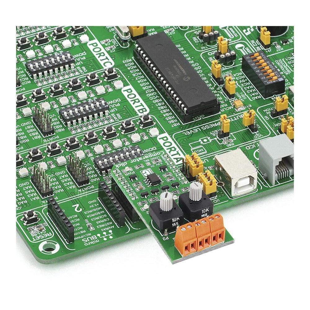
Depending on the development board you are using, you may need a USB UART click, USB UART 2 click or RS232 click to connect to your PC, for development systems with no UART to USB interface available on the board. The terminal available in all MikroElektronika compilers, or any other terminal application of your choice, can be used to read the message
Comparator Click Board
Frequently Asked Questions
Have a Question?
Be the first to ask a question about this.