


Mikroelektronika d.o.o.
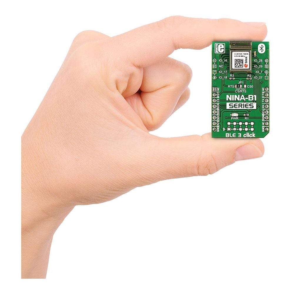
BLE 3 Click Board™
BLE 3 Click Board™
SKU: MIKROE-2471
Couldn't load pickup availability

Overview
The BLE 3 Click Board™ is a quick and simple solution if you want to add Bluetooth Low Energy to your project. It features the NINA-B1 Bluetooth 4.2 module, from u-blox.
This Click Board™ also comes with an integrated antenna mounted on the PCB.
Downloads
Built-In RTC Daves Energy
One of the standout features of the NINA-B1 module is its real time counter functionality. This counter can be used to generate precisely timed BLE advertising events (broadcasting packets to every device around), without involving the main MCU. The RTC can be operated in standby mode as well — further lowering the already low power consumption.
Designed for IoT and Smart Devices
BLE – also known as Bluetooth Low Energy is designed for sensors and smart devices that send out small pieces of information in regular intervals and need to have very low power consumption. For example our Hexiwear uses BLE for wireless communication. You can combine the BLE 3 Click Board™ with one of our sensor clicks, like the Air quality click, and get notified what the air quality of your home or office is all the time.
Power Saving Modes
For really low power consumption there are different power saving modes to conserve battery life – standby mode and power off mode. The module can spend most of the time in power off mode and wake up periodically only to send small packages of data.
The ADC featured on the BLE 3 Click Board™ can sample up to 200 kHz using different inputs as sample triggers and it supports 8/10/12-bit resolution.
For applications that require it, u-blox offers Apple iOS and Google Android connectivity.
The BLE 3 Click Board™ communicates with the target board MCU through the UART, SPI and I2C interface, with the addition of 7 GPIO pins. It uses 3.3V power supply only.
SPECIFICATIONS
| Type | BT/BLE |
| Applications | Medical equipment and fitness applications, IoT devices, home automation, smart energy, etc. |
| On-board modules | NINA-B1 Bluetooth 4.2 module |
| Key Features | LED indicates power is on, Antenna power +10dBm, 2.4 GHz frequency band |
| Interface | GPIO,I2C,SPI,UART |
| Compatibility | mikroBUS |
| Click board size | M (42.9 x 25.4 mm) |
| Input Voltage | 3.3V |
Display
Also known as Bluetooth Low Energy, BLE is intended for small smart devices like home automation sensor and fitness applications that need to have really low power consumption and long battery life. The BLE 3 Click Board™ communicates with the target board MCU through the UART, SPI and I2C interface, with the addition of 7 GPIO pins. It uses 3.3V power supply only.
The NINA-B1 module has different power saving modes to conserve battery life – standby mode and power off mode. The module usually spends most of the time in power off mode (it is the primary mode) and wakes up to send small packages of data, and then powers off again. The following events can be used to bring the module out of standby-mode:
- External wake-up event
- RTC event
- Analog or digital sensor event (programmable voltage level or edge detection)
During standby mode, the module is clocked at 32 kHz reference clock, which is generated by an internal 32 kHz oscillator.
The module is fully Bluetooth qualified and provides global modular approval. The ADC can sample up to 200 kHz using different inputs as sample triggers and it supports 8/10/12 bit resolution. Any of the 8 analog inputs can be used both as single-ended inputs and as differential pairs for measuring the voltage across them. The ADC supports full 0 V to VCC input range.
The NINA-B112 modules have an integrated antenna mounted on the PCB (10.0 x 14.0 mm). The RF signal pin is not connected to any signal path. You can configure NINA-B1 modules through U-Blox S-Center toolbox software using AT commands. The s-center evaluation software is available free of charge and can be downloaded from the U-Blox website.
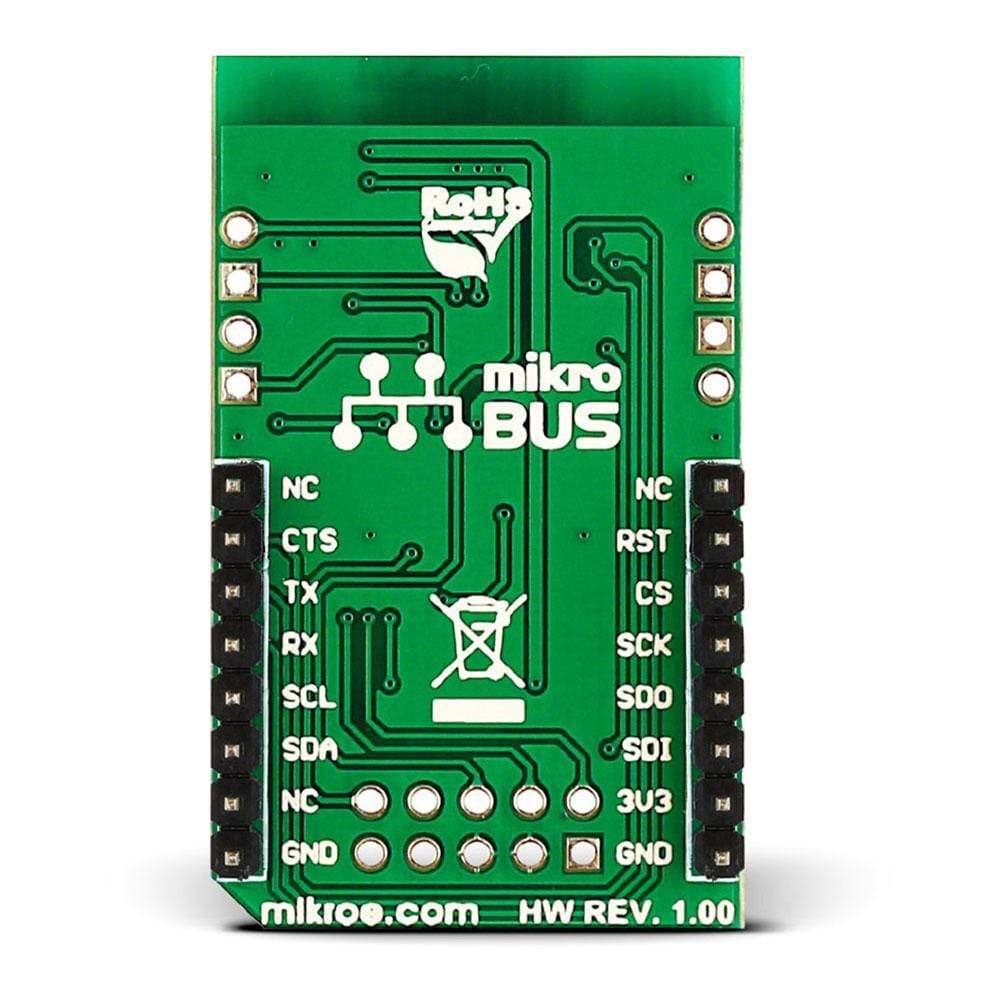
PINOUT DIAGRAM
This table shows how the pinout on the BLE 3 Click Board™ ccorresponds to the pinout on the mikroBUS™ socket (the latter shown in the two middle columns).
| Notes | Pin | Pin | Notes | ||||
|---|---|---|---|---|---|---|---|
| NC | 1 | AN | PWM | 16 | NC | ||
| Active-high Reset pin | RST | 2 | RST | INT | 15 | RTS | UART request to send |
| UART clear to send | CS/CTS | 3 | CS | RX | 14 | TX | |
| SPI0 SCLK | 4 | SCK | TX | 13 | RX | ||
| SPI0 MISO | 5 | MISO | SCL | 12 | SCL | ||
| SPI0 MOSI | 6 | MOSI | SDA | 11 | SDA | ||
| Power supply | +3.3V | 7 | +3.3V | +5V | 10 | NC | |
| Ground | GND | 8 | GND | GND | 9 | GND | Ground |
The board also has an additional pinout with 7 GPIOs:
| Name | I/O | Description |
|---|---|---|
| IO_7 | I/O | GPIO intended for use with a push-button switch. |
| IO_16 | I/O | Analog function enabled GPIO |
| IO_17 | I/O | Analog function enabled GPIO. |
| IO_18 | I/O | Analog function enabled GPIO |
| IO_27 | I/O | Analog function enabled GPIO |
| IO_28 | I/O | NFC pin 1 |
| IO_29 | I/O | NFC pin 2 |
| General Information | |
|---|---|
Part Number (SKU) |
MIKROE-2471
|
Manufacturer |
|
| Physical and Mechanical | |
Weight |
0.019 kg
|
| Other | |
EAN |
8606015079189
|
Frequently Asked Questions
Have a Question?
Be the first to ask a question about this.