


Mikroelektronika d.o.o.
Watchdog Click-Platine
Watchdog Click-Platine
SKU: MIKROE-4416
Verfügbarkeit für Abholungen konnte nicht geladen werden


Overview
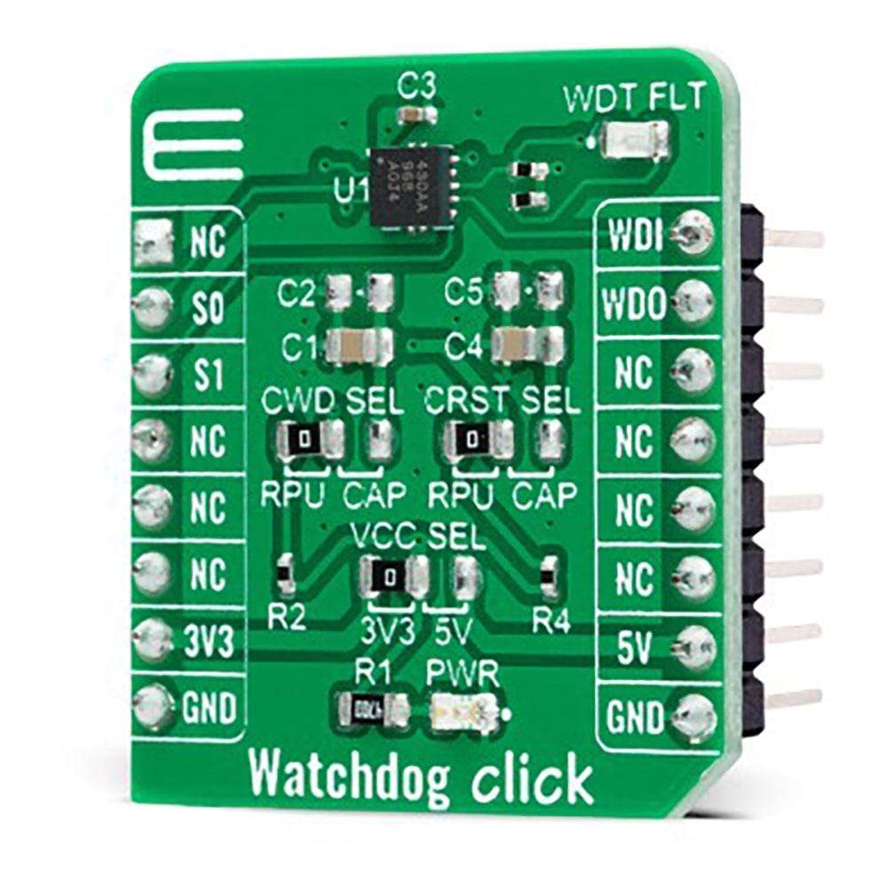
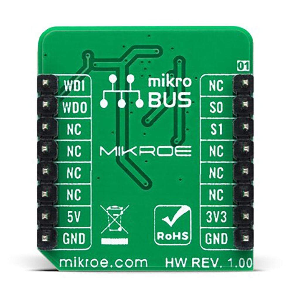
The Watchdog Click Board™ is a compact add-on board that contains a simple countdown timer for a wide variety of applications. This board features the TPS3430, a standalone watchdog timer with a programmable watchdog window and programmable reset delay from Texas Instruments. The TPS3430 has the watchdog output reset delay set by factory-programmed default delay settings or programmed by an external capacitor. It achieves 2.5% timing accuracy at the typical temperature of 25°C and can be disabled via two SET pins to avoid undesired watchdog timeouts during the development process or Power-On. This Click Board™ can be used as a countdown timer in MCU, DSP, FPGA, ASIC, and many more.
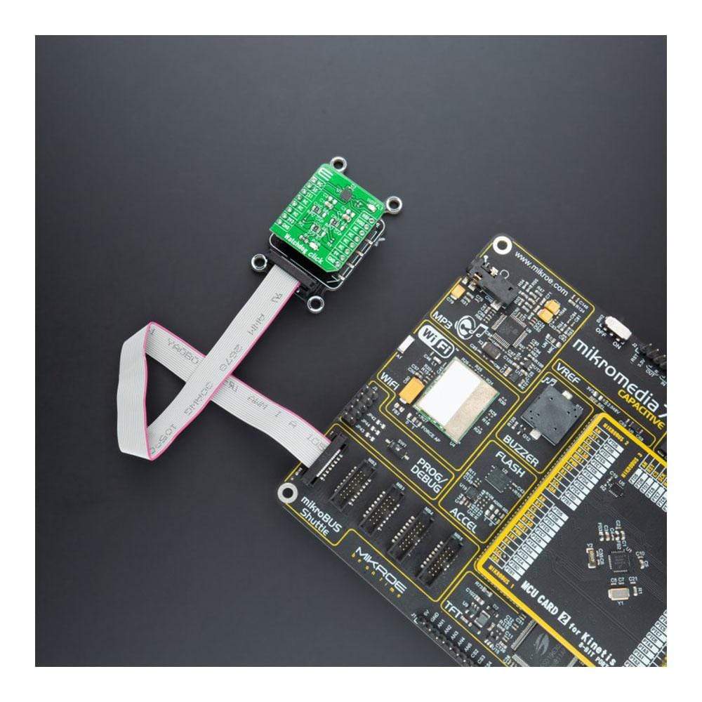
The Watchdog Click Board™ is supported by a mikroSDK compliant library, which includes functions that simplify software development. This Click Board™ comes as a fully tested product, ready to be used on a system equipped with the mikroBUS™ socket.
Downloads
Der Watchdog Click Board™ ist eine kompakte Zusatzplatine, die einen einfachen Countdown-Timer für eine Vielzahl von Anwendungen enthält. Diese Platine verfügt über den TPS3430, einen eigenständigen Watchdog-Timer mit einem programmierbaren Watchdog-Fenster und einer programmierbaren Reset-Verzögerung von Texas Instruments. Beim TPS3430 wird die Reset-Verzögerung des Watchdog-Ausgangs durch werkseitig programmierte Standardverzögerungseinstellungen eingestellt oder durch einen externen Kondensator programmiert. Es erreicht eine Zeitgenauigkeit von 2,5 % bei der typischen Temperatur von 25 °C und kann über zwei SET-Pins deaktiviert werden, um unerwünschte Watchdog-Timeouts während des Entwicklungsprozesses oder beim Einschalten zu vermeiden. Dieses Click Board™ kann als Countdown-Timer in MCU, DSP, FPGA, ASIC und vielen mehr verwendet werden.
Das Watchdog Click Board™ wird durch eine mikroSDK-kompatible Bibliothek unterstützt, die Funktionen enthält, die die Softwareentwicklung vereinfachen. Dieses Click Board™ wird als vollständig getestetes Produkt geliefert und ist bereit für den Einsatz auf einem System, das mit der mikroBUS™-Buchse ausgestattet ist.
| General Information | |
|---|---|
Part Number (SKU) |
MIKROE-4416
|
Manufacturer |
|
| Other | |
EAN |
8606027381669
|
Frequently Asked Questions
Have a Question?
Be the first to ask a question about this.