Timer-Click-Platine
Timer-Click-Platine
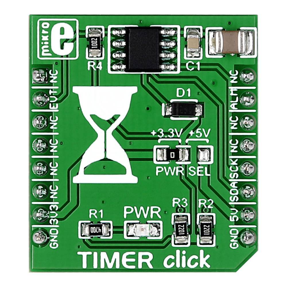
Der Timer Click Board™ ist eine MikroBUS-Zusatzkarte mit dem DS1682-Gesamtzeitrekorder von Maxim. Das Hauptmerkmal des IC ist sein Zeitzähler (ETC), der in Verbindung mit dem ALARM-Pin verwendet wird.
The Timer Click Board™ is a mikroBUS™ add-on board with Maxim's DS1682 total elapsed time recorder. The main feature of the IC is its elapsed time counter (ETC) used in conjunction with the ALARM pin. Whenever the EVENT pin is held high, the ETC will track time in quarter second resolution. Once the EVENT pin is set to logic low, the time data will be written in the IC's non volatile EEPROM. The next time the EVENT pin is pulled high, the timer will pick up where it left and continue measuring accumulated time. The upper limit is 34 years. In practical applications, the ALARM pin will be utilized to set off a flag once a certain threshold of accumulated time is reached. The alarm flag is one time programmable.
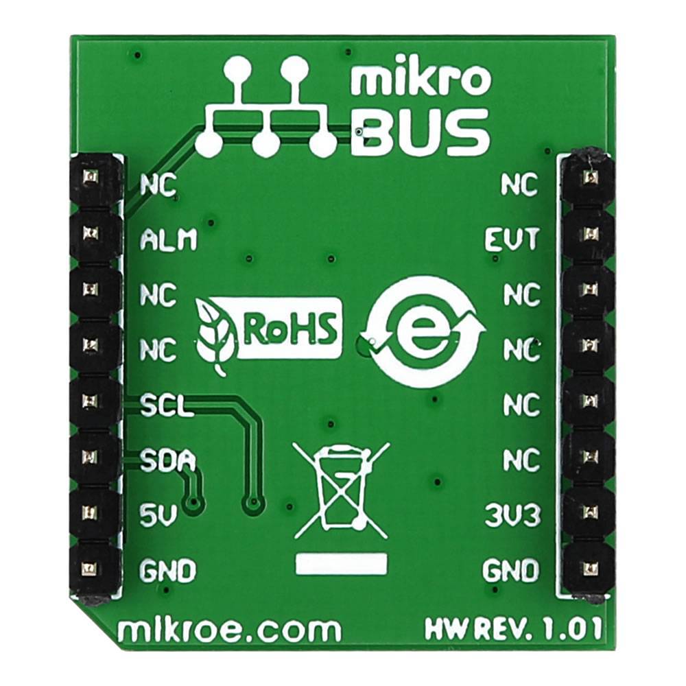
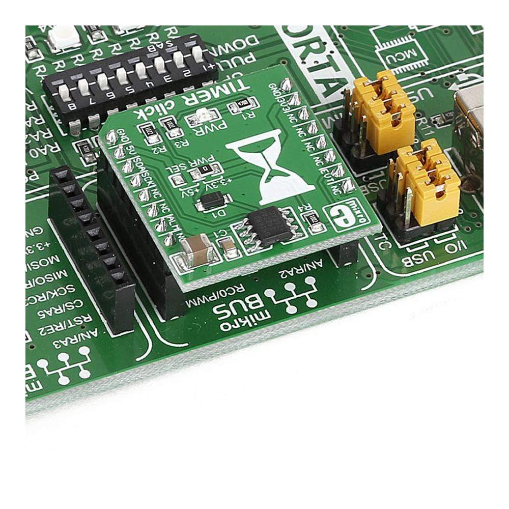
The board communicates with the target MCU through the mikroBUS™ I2C interface, with two additional pins: ALARM (in place of default INT) and EVENT (in place of RST). Designed to use either a 3.3V or a 5V power supply only.
Software Support
Application Task
This is a example which demonstrates the use of Timer Click Board™. The Timer Click Board™ communicates with register via I2C by write to register and read from register, display time ( days, hours, minutes and seconds ) which we
received reading from the target register address of DS1682 total > elapsed time recorder. Results are being sent to the USART Terminal where you can track > their changes. All data logs write on usb uart changes for every 1 sec.
void application_task ( )
{
static uint8_t time_seconds_new = 0xFF;
uint8_t time_hours;
uint8_t time_minutes;
uint8_t time_seconds;
uint16_t time_days;
timer_get_time( &timer, &time_days, &time_hours, &time_minutes, &time_seconds );
if ( time_seconds_new != time_seconds )
{
log_printf
(
&logger, " %d days %d:%d:%d \r\n",
time_days,
time_hours,
time_minutes,
time_seconds
);
log_printf( &logger, "------------------\r\n" );
time_seconds_new = time_seconds;
}
Delay_ms( 1 );
}
The full application code, and ready to use projects can be installed directly form compilers IDE(recommneded) or found on LibStock page or mikroE GitHub account.
Other mikroE Libraries used in the example:
- MikroSDK.Board
- MikroSDK.Log
- Click.Timer
Additional notes and informations
Depending on the development board you are using, you may need a USB UART click, USB UART 2 Click or RS232 Click to connect to your PC, for development systems with no UART to USB interface available on the board. The terminal available in all Mikroelektronika compilers, or any other terminal application of your choice, can be used to read the message.
Timer-Click-Platine
Frequently Asked Questions
Have a Question?
Be the first to ask a question about this.