
Tag-Connect, LLC
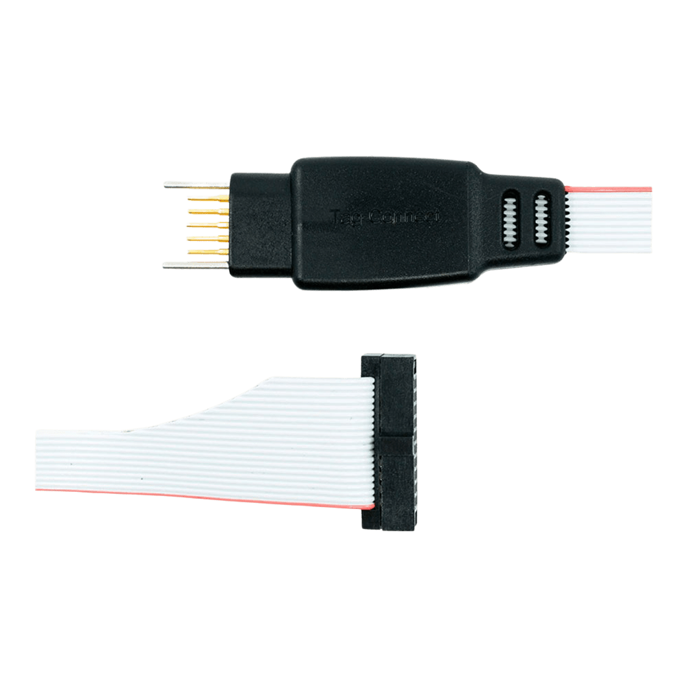
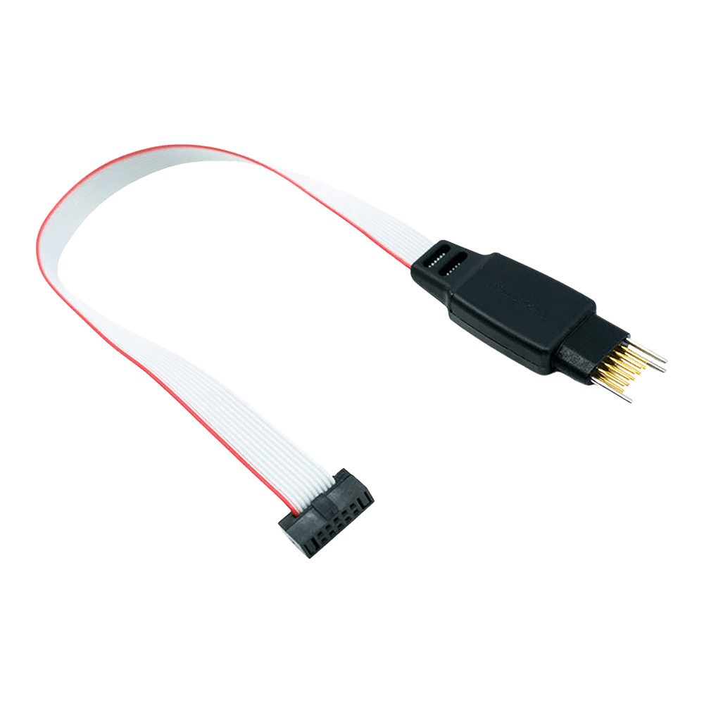
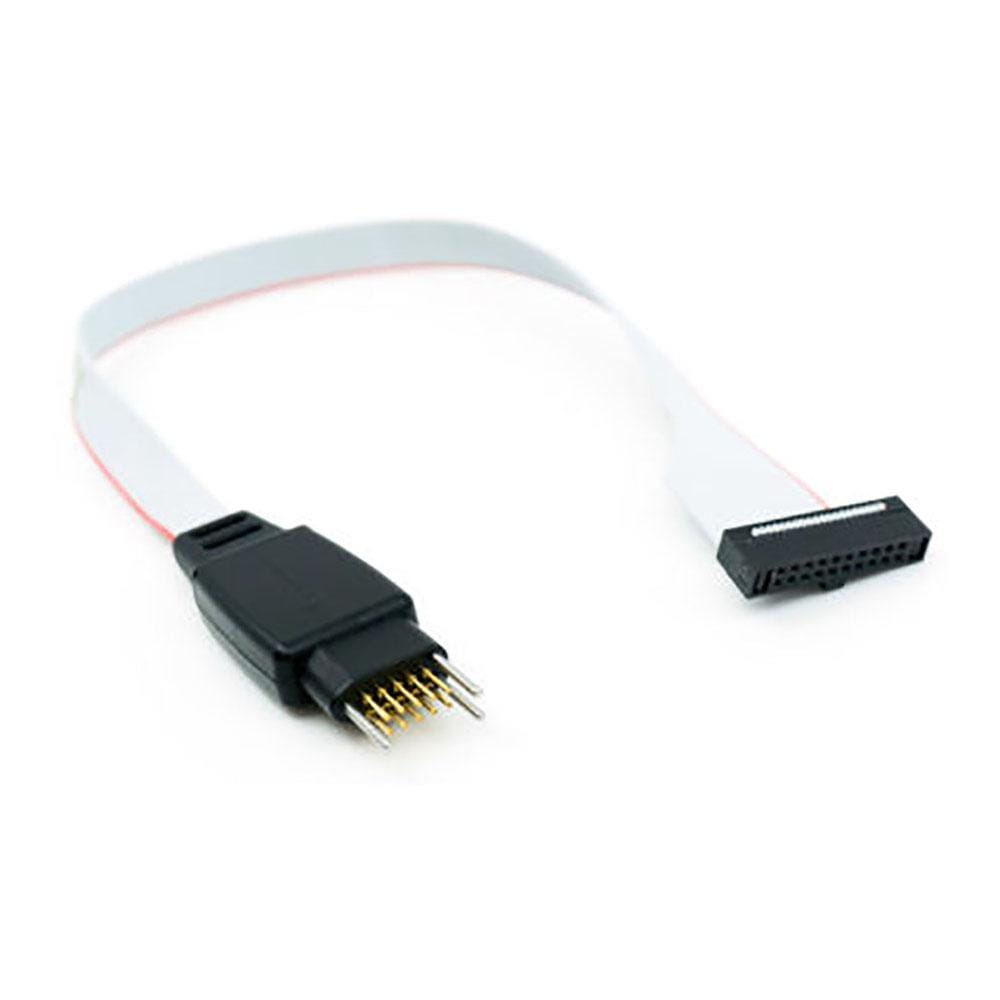
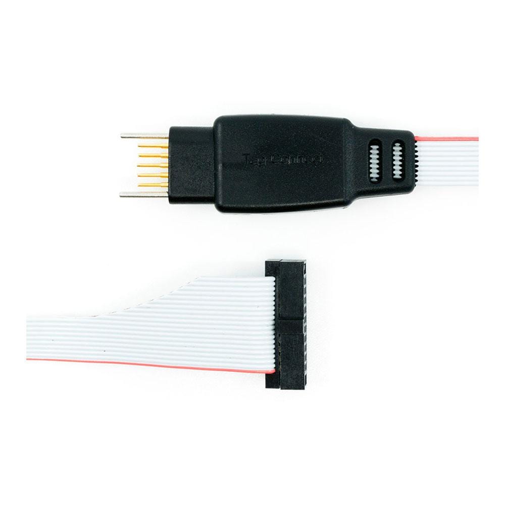
Tag-Connect TC2050-IDC-050-ALL-20 10-poliges Kabel für 20-poligen Cortex Debug 0,05 Zoll (mit oder ohne Rastbeine)
Tag-Connect TC2050-IDC-050-ALL-20 10-poliges Kabel für 20-poligen Cortex Debug 0,05 Zoll (mit oder ohne Rastbeine)
SKU: TC2050-IDC-050-ALL-20
€85,95 EUR exc tax
Suggested Add-Ons
Optional. Tick any you need. One of each is added to your cart with this item, whatever the quantity.
Check and Add to Cart
Confirm the price and stock for your selection, set the quantity, then press Add to Cart.
Zahlungsmethoden
- Banküberweisung
Verfügbarkeit für Abholungen konnte nicht geladen werden
Key Features
Overview
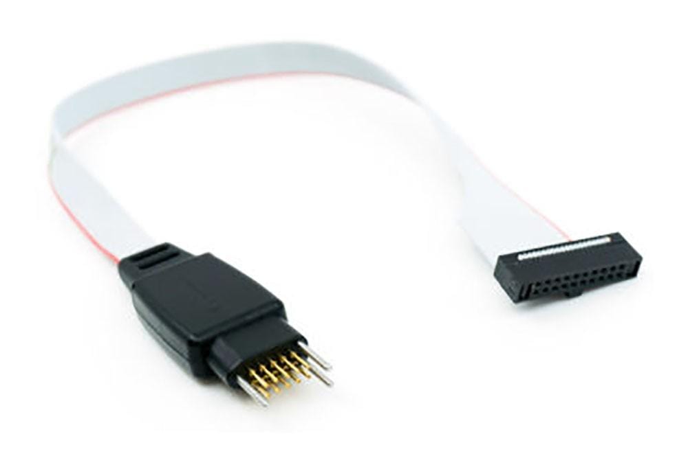
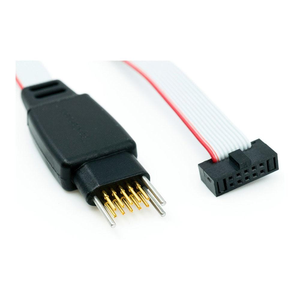
The Tag-Connect TC2050-IDC-050-ALL-20 links a probe with the 20-pin 0.05 in Cortex Debug + ETM header to ten pads on your PCB. Pins 1 to 10 are wired 1-to-1, so SWD and JTAG reach the target; pins 11 to 20 (parallel trace, extra grounds and, on some probes, target power) are not connected.
Choose the head in the options above.
The Legged version clips into the footprint and stays in place without a fixture. The No Legs version needs about 0.03 sq in and is held by hand, with a TC2050-CLIP or in a fixture. For a 10-pin 0.05 in probe use the TC2050-IDC-050-ALL.
Downloads
Zehn Pads auf Ihrer Leiterplatte zu einer 20-poligen Cortex-Debug-Probe im 0,05-Zoll-Raster
Das Tag-Connect TC2050-IDC-050-ALL-20 verbindet einen Debugger mit 20-poligem Cortex-Debug-+-ETM-Anschluss im 0,05-Zoll-Raster (1,27 mm), dem Mikro-Header im Samtec-FTSH-110-Stil, mit einem 10-Pad-TC2050-Footprint auf Ihrer Leiterplatte, ohne dass ein Steckverbinder bestückt wird. Die Pins 1 bis 10 sind 1:1 mit den zehn Pads verbunden, sodass SWD und JTAG das Zielsystem erreichen. Die Pins 11 bis 20, die am 20-poligen Anschluss Trace-Takt und Trace-Daten, zusätzliche Massen und bei manchen Probes eine Versorgung für das Zielsystem führen, sind nicht beschaltet.
Optionen
| Option | Auswahl | Details |
|---|---|---|
| Kopf | Mit Rastbeinen | Vier Rastbeine rasten in Löcher der Leiterplatte ein, sodass das Kabel von selbst hält |
| Kopf | Ohne Rastbeine | Keine Rastlöcher; Footprint etwa 0,03 Quadratzoll; von Hand, mit einem TC2050-CLIP oder in einer Vorrichtung halten |
TC2050-IDC-050-ALL-20 Pinbelegung
TC2050-Pad n führt auf Steckerpin n für die Pins 1 bis 10. Die Signale folgen dem Arm-Cortex-Debug-Anschluss:
| Pad und Pin | Signal | Pad und Pin | Signal |
|---|---|---|---|
| 1 | VTref | 2 | SWDIO / TMS |
| 3 | GND | 4 | SWCLK / TCK |
| 5 | GND | 6 | SWO / TDO |
| 7 | Kodierung (kein Signal) | 8 | TDI |
| 9 | GNDDetect | 10 | nRESET |
Die Steckerpins 11 bis 20 sind nicht beschaltet, daher ist paralleler Trace (TRACECLK und TRACEDATA) über dieses Kabel nicht verfügbar, und eine Probe, die das Zielsystem über die Pins 11 und 13 versorgt, kann es über dieses Kabel nicht versorgen. SWO an Pin 6 ist verbunden.
Auf dem Footprint sind die Pads entlang einer Reihe von 1 bis 5 und entlang der anderen von 6 bis 10 zurück nummeriert, sodass Pad 10 gegenüber Pad 1 liegt. Sie sind nicht wie am Header nach geraden und ungeraden Nummern angeordnet: Halten Sie sich an die Footprint-Zeichnung.
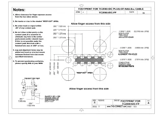
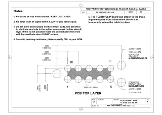
Leiterplatten-Footprint: zehn Kontaktpads im 0,05-Zoll-Raster und drei Ausrichtlöcher; der Footprint mit Rastbeinen hat zusätzlich vier Rastlöcher. Keine Lotpaste auf die Kontaktpads. Die Footprint-Zeichnungen finden Sie in den Datenblättern TC2050-IDC (mit Rastbeinen) und TC2050-IDC-NL (ohne Rastbeine) unter Downloads. Siehe auch unseren Tag-Connect-Kabelratgeber.
Federkontakte
Tag-Connect gibt für die TC2050-Federkontaktstifte über 100.000 Steckvorgänge an. Der 0,05-Zoll-Stecker nutzt ein Flachbandkabel mit feinem Raster und dünnen Leitern, die laut Tag-Connect bei wiederholtem Biegen mit der Zeit brechen können. Vermeiden Sie daher scharfe Knicke und wiederholtes Biegen am Stecker.
Für wen es gedacht ist
Für Entwickler, die Arm-Cortex-Leiterplatten über SWD oder JTAG mit einer Probe mit 20-poligem Cortex-Debug-+-ETM-Anschluss im 0,05-Zoll-Raster programmieren oder debuggen und keinen Debug-Header auf der Leiterplatte wollen.
| Bausteinfamilie | Debugger oder Programmiergerät | Anschluss |
|---|---|---|
| Arm-Cortex-M-Bausteine, SWD oder JTAG | Keil ULINKpro | Direkt, am 20-poligen Cortex-Debug-+-ETM-Anschluss im 0,05-Zoll-Raster im Inneren der Probe (Abdeckung abnehmen) |
| Arm-Cortex-Bausteine, SWD oder JTAG | IAR I-jet | Direkt, am MIPI-20-Anschluss (20-polig, 0,05 Zoll) des I-jet; paralleler Trace wird nicht übertragen |
Keil ULINK2 und ULINKplus haben den 10-poligen Cortex-Debug-Anschluss im 0,05-Zoll-Raster: Verwenden Sie stattdessen das TC2050-IDC-050-ALL.
Einschränkungen
Nicht das richtige Kabel, wenn Sie parallelen Trace benötigen: Nur die Pins 1 bis 10 sind beschaltet. Nicht für einen Debugger, der nur den 20-poligen Arm-JTAG-Anschluss im 0,1-Zoll-Raster hat (verwenden Sie das TC2050-IDC mit dem Adapter TC2050-ARM2010), und nicht für den Microchip Atmel-ICE (verwenden Sie das TC2050-IDC-050-ALL mit der Option Flachbandstecker LEMTA, bei der der Stecker umgekehrt montiert ist).
Versionen im Vergleich
| Teilenummer | Kopf | Footprint | Am besten für |
|---|---|---|---|
| TC2050-IDC-050-ALL-20 | Mit Rastbeinen | Zehn Pads, drei Ausrichtlöcher und vier Rastlöcher | Entwicklung und Debugging: rastet ein und bleibt freihändig verbunden |
| TC2050-IDC-NL-050-ALL-20 | Ohne Rastbeine | Zehn Pads und drei Ausrichtlöcher, etwa 0,03 Quadratzoll | Serienprogrammierung oder Debugging mit einem TC2050-CLIP; kleinster Footprint |
Beide Versionen nutzen dasselbe Kontaktmuster mit zehn Pads und dieselbe Verdrahtung; nur der Kopf unterscheidet sich.
Welches Kabel passt zu Ihrem Debugger? Siehe unseren Tag-Connect-Kabelratgeber.
| Ordering information | |
|---|---|
| Part number (SKU) | TC2050-IDC-050-ALL-20 |
| Manufacturer | Tag-Connect, LLC |
| EAN | 5055383665464 |
| Warranty | 6 Monate |
| Shipping weight | 0.1 kg |
- 1 ×Tag-Connect TC2050-IDC-050-ALL-20 cable, Legged or No Legs as selected
Cable only. No debugger, adapter, retaining clip or fixture is included. On the No Legs version, the TC2050-CLIP retaining clip and the TC-MOUNT-10 fixture bracket are offered as add-ons.
Questions and Answers
-
How Do I Create the PCB Footprint for This Cable?
Download the TC2050-IDC (Legged) or TC2050-IDC-NL (No Legs) datasheet for exact pad dimensions, hole sizes and spacing. Both are under Downloads on this page.
-
Is This Cable Suitable for Production Programming?
Yes. Tag-Connect recommends the No Legs version (TC2050-IDC-NL-050-ALL-20) for production, where short connection times matter, and the Legged version for development. Tag-Connect rates the TC2050 spring pins for over 100,000 operations, and notes that the fine 0.05 in ribbon can break with repeated flexing.
-
Can I Use This with 3.3 V Target Systems?
Yes. The cable is passive, so it works at any target voltage your debugger supports. Pin 1 carries the target voltage reference to the debugger; it is not a power supply.
-
What Signals Are Available on the TC2050 Footprint?
Pins 1 to 10 of the 20-pin connector pass straight through to the ten pads: VTref (1), SWDIO/TMS (2), GND (3 and 5), SWCLK/TCK (4), SWO/TDO (6), key (7, no signal), TDI (8), GNDDetect (9) and nRESET (10). Pins 11 to 20 are not connected.
-
How Does This Compare to Traditional 20-pin JTAG Headers?
It removes the connector cost of a traditional 20-pin JTAG header, carrying the JTAG/SWD signals on pins 1-10 of the header (pins 11-20 are not connected).
Traditional 20-pin header This cable and footprint Connector on the board Fitted on every board None; per-board cost of the footprint is zero Board space Depends on the header About 0.03 sq in for the No Legs footprint Signals carried Pins 1-20 Pins 1-10 (pins 11-20, including parallel trace, not connected) -
What Debuggers Are Compatible with the TC2050-IDC-050-ALL-20 Cable?
Tag-Connect recommends it for the IAR I-jet and the Keil ULINKpro (on the ULINKpro's internal 20-pin header, under the cover), and for other debuggers with the 20-pin 0.05 in Cortex Debug + ETM (MIPI-20) connector, the Samtec FTSH-110-01 style micro-header. The Keil ULINK2 has the 10-pin 0.05 in Cortex Debug connector, so use the TC2050-IDC-050-ALL with it.
-
How Does This Differ From the Standard TC2050-IDC-050 Cable?
This cable connects all 10 TC2050 pins one-to-one, whereas the standard TC2050-IDC-050 leaves two pins open.
Cable TC2050 pins 5 and 9 Other pins TC2050-IDC-050-ALL-20 (this cable) Connected All 10 connected 1-1; pins 11-20 of the 20-pin connector not connected TC2050-IDC-050 Not connected Pins 1-4, 6-8 and 10 connected -
What PCB Thickness Range Is Supported?
Tag-Connect does not publish a thickness range for the standard legs. Its LONGLEGS version is recommended for boards over 1.6 mm (0.063 in) thick and works up to 3.2 mm (0.126 in), so treat about 1.6 mm as the practical limit for the standard legs.
Legs PCB thickness Standard legs (Legged version) Up to about 1.6 mm (0.063 in); no range published TC2050-IDC-LONGLEGS Over 1.6 mm, up to 3.2 mm (0.126 in) Tag-Connect lists no LONGLEGS version of this 20-pin cable; its long-leg TC2050 cable is the TC2050-IDC-LONGLEGS.
-
Can I Use This Cable with STM32 Microcontrollers?
Yes, provided your debugger has a Cortex-20 header with 0.05 in pitch. The cable carries the Cortex debug signals on pins 1-10, so check that your debugger uses that connector. Tag-Connect's STM32 and ST-LINK solutions use other cables (STDC14 or ARM20).
-
What's the Difference Between the Legged and No Legs Versions?
The Legged version has four plastic legs that latch into the PCB for a secure hands-free connection. The No Legs version must be held by hand or used with the TC2050-CLIP.
Legged No Legs Hold on the PCB Secures itself with plastic legs Held by hand, or with a TC2050-CLIP Footprint Adds four leg holes Pads and alignment holes only, about 0.03 sq in Tag-Connect suggests it for Development needing a secure connection over time Production programming, especially short one-off operations


No questions match your search.
