


Mikroelektronika d.o.o.
Stepper 4 Click-Platine
Stepper 4 Click-Platine
SKU: MIKROE-2748
Verfügbarkeit für Abholungen konnte nicht geladen werden
Overview
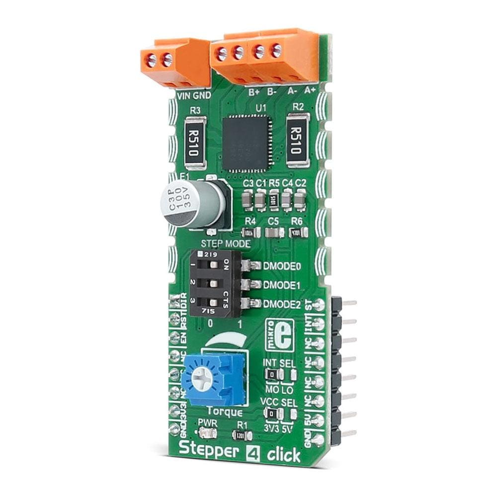
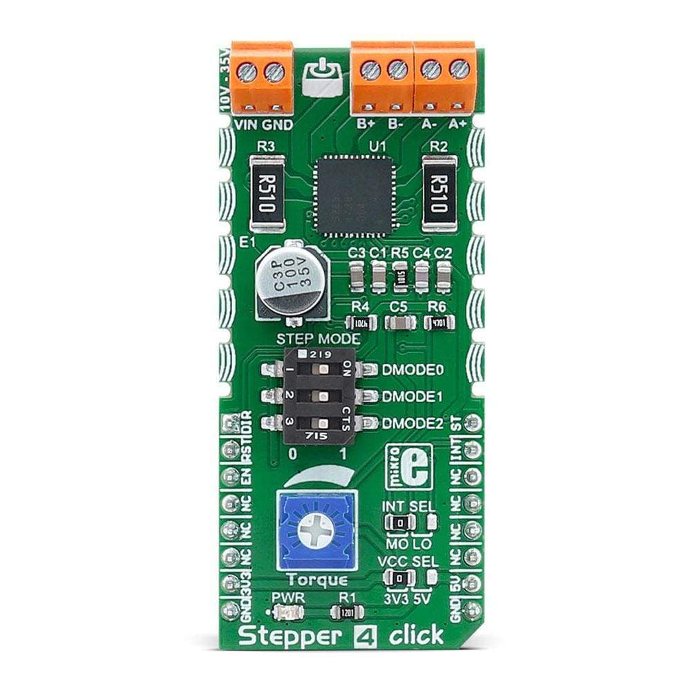
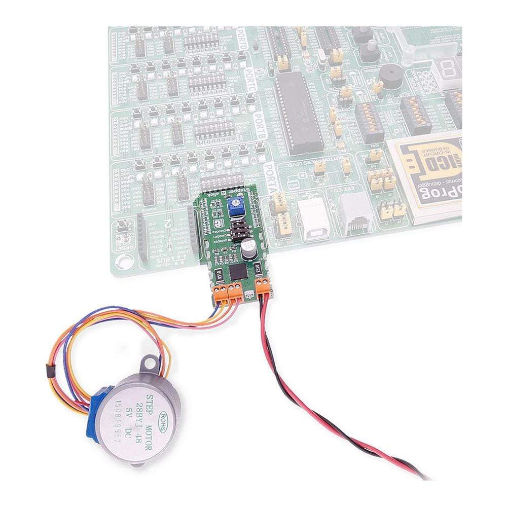
The Stepper 4 Click Board™ can be used for driving a stepper motor and controlling its step resolution, rotation direction, and time between the steps. It has an output drive capability of 2A.
The Click Board™ carries TB67S269FTG, a two-phase bipolar stepping motor driver from Toshiba. Stepper 4 Click Board™ is designed to run on either 3.3V or 5V power supply. It communicates with the target microcontroller over the following pins on the MikroBUSline: AN, RST, CS, PWM, INT.
Downloads
Das Stepper 4 Click Board™ kann zum Antreiben eines Schrittmotors und zur Steuerung seiner Schrittauflösung, Drehrichtung und Zeit zwischen den Schritten verwendet werden. Es verfügt über eine Ausgangsantriebskapazität von 2 A.
Das Click Board™ enthält TB67S269FTG, einen zweiphasigen bipolaren Schrittmotortreiber von Toshiba. Stepper 4 Click Board™ ist für den Betrieb mit 3,3 V oder 5 V Stromversorgung ausgelegt. Es kommuniziert mit dem Zielmikrocontroller über die folgenden Pins auf der MikroBUSline: AN, RST, CS, PWM, INT.
| General Information | |
|---|---|
Part Number (SKU) |
MIKROE-2748
|
Manufacturer |
|
| Physical and Mechanical | |
Weight |
0.024 kg
|
| Other | |
EAN |
8606018711352
|
Frequently Asked Questions
Have a Question?
Be the first to ask a question about this.