


Mikroelektronika d.o.o.
RS485 5V Click-Platine
RS485 5V Click-Platine
SKU: MIKROE-925
Verfügbarkeit für Abholungen konnte nicht geladen werden

Overview
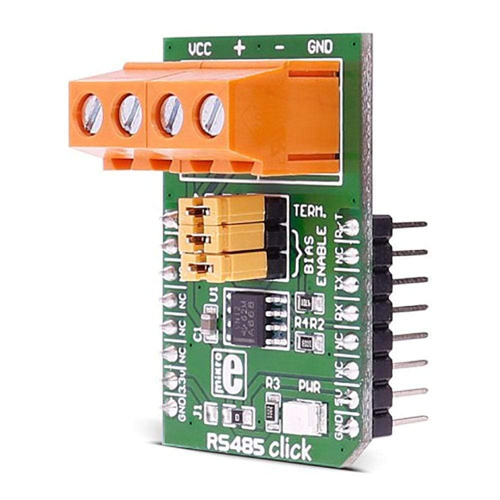
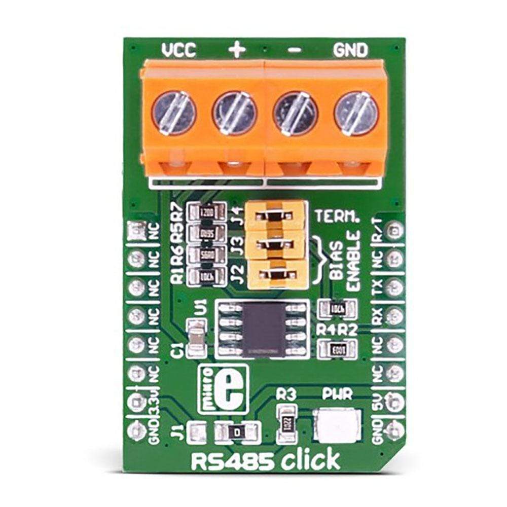
The RS485 5 Click Board™ is equipped with the MAX485, low-power, slew-rate-limited transceiver for RS-485 and RS-422 communication, from Maxim Integrated. This device supports half-duplex RS-485 communication and can be used as an interface between the TTL level UART and the RS485 communication bus. Thanks to the low power consumption and reduced slew-rate drivers that minimize EMI and reduce reflections caused by improperly terminated cables, error-free data transmission up to 250kbps is supported.
The RS485 5 Click Board™ is perfectly suitable for EMI-Sensitive Applications, such as industrial-control local area networks, building automation, HVAC systems, and many more.
Downloads
Der RS485 5 Click Board™ ist mit dem MAX485, einem stromsparenden Transceiver mit begrenzter Anstiegsrate für RS-485- und RS-422-Kommunikation von Maxim Integrated ausgestattet. Dieses Gerät unterstützt Halbduplex-RS-485-Kommunikation und kann als Schnittstelle zwischen dem TTL-Pegel-UART und dem RS485-Kommunikationsbus verwendet werden. Dank des geringen Stromverbrauchs und der Treiber mit reduzierter Anstiegsrate, die elektromagnetische Störungen minimieren und Reflexionen durch unsachgemäß angeschlossene Kabel reduzieren, wird eine fehlerfreie Datenübertragung mit bis zu 250 kbit/s unterstützt.
Der RS485 5 Click Board™ eignet sich perfekt für EMI-empfindliche Anwendungen wie lokale Netzwerke zur industriellen Steuerung, Gebäudeautomatisierung, HLK-Systeme und vieles mehr.
| General Information | |
|---|---|
Part Number (SKU) |
MIKROE-925
|
Manufacturer |
|
| Physical and Mechanical | |
Weight |
0.034 kg
|
| Other | |
EAN |
8606015073262
|
Frequently Asked Questions
Have a Question?
Be the first to ask a question about this.