


Mikroelektronika d.o.o.
RN4871 Click-Platine
RN4871 Click-Platine
SKU: MIKROE-2544
Verfügbarkeit für Abholungen konnte nicht geladen werden
Overview
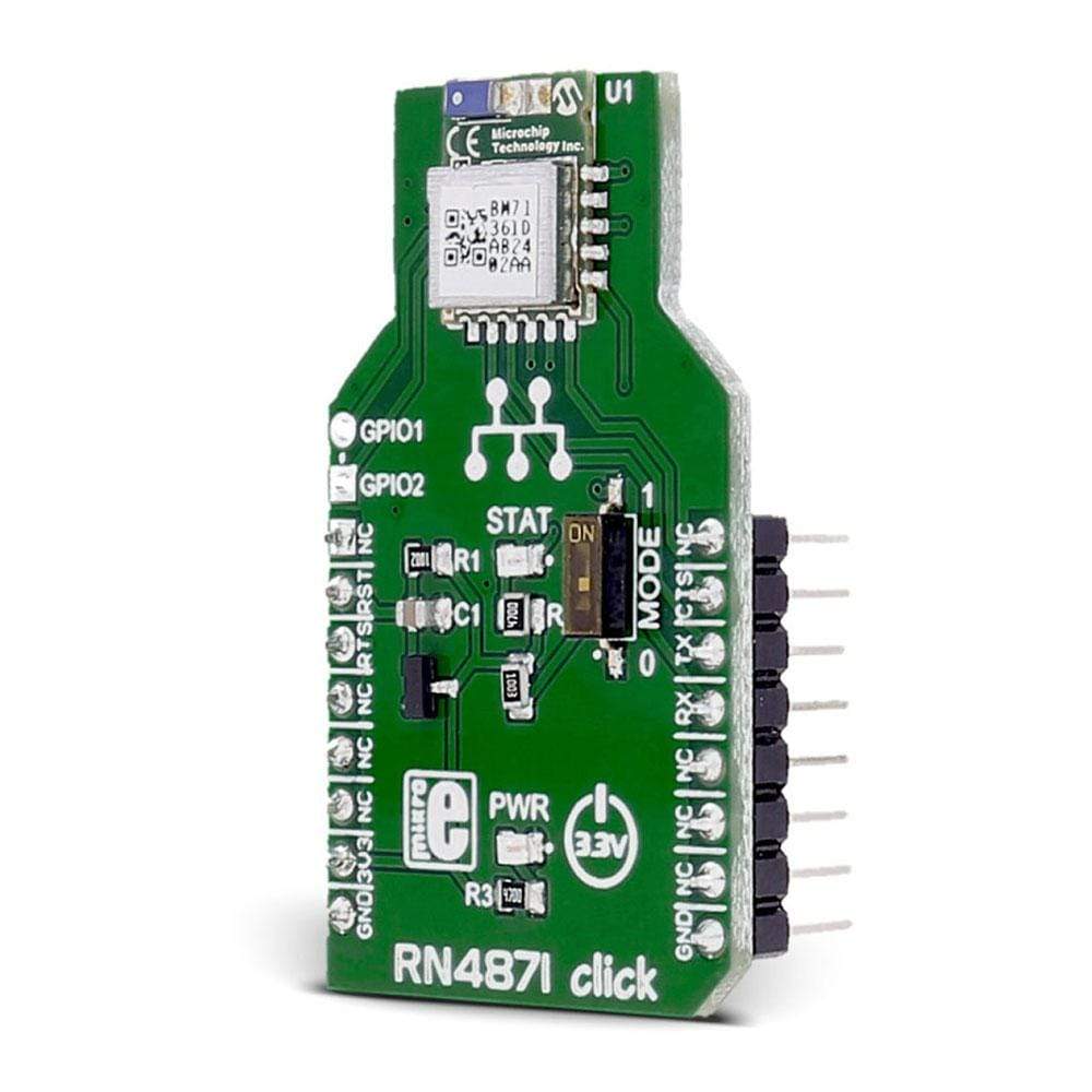
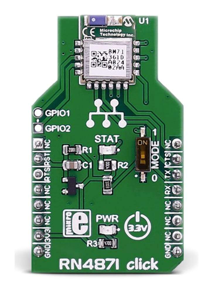
The RN4871 Click Board™ carries the RN4871 Bluetooth® 4.2 low energy module from Microchip.
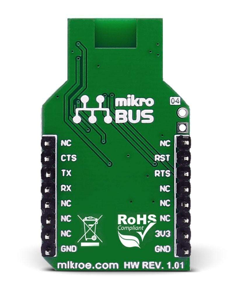
The Click Board™ is designed to run on a 3.3V power supply. It uses ASCII Command Interface over UART for communication with target microcontroller, with additional functionality provided by the following pins on the mikroBUS™ line: RST, CS, and INT.
Downloads
Das RN4871 Click Board™ enthält das RN4871 Bluetooth® 4.2 Low Energy-Modul von Microchip.
Das Click Board™ ist für den Betrieb mit einer 3,3-V-Stromversorgung ausgelegt. Es verwendet die ASCII-Befehlsschnittstelle über UART zur Kommunikation mit dem Zielmikrocontroller, wobei zusätzliche Funktionen durch die folgenden Pins auf der mikroBUS™-Leitung bereitgestellt werden: RST, CS und INT.
| General Information | |
|---|---|
Part Number (SKU) |
MIKROE-2544
|
Manufacturer |
|
| Physical and Mechanical | |
Weight |
0.02 kg
|
| Other | |
EAN |
8606018710515
|
Frequently Asked Questions
Have a Question?
Be the first to ask a question about this.