


Mikroelektronika d.o.o.
RMS-zu-DC-Click-Platine
RMS-zu-DC-Click-Platine
SKU: MIKROE-3311
Verfügbarkeit für Abholungen konnte nicht geladen werden


Overview
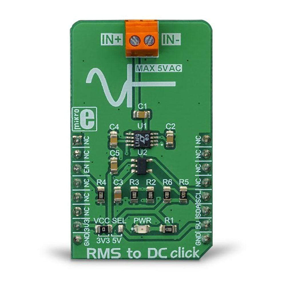
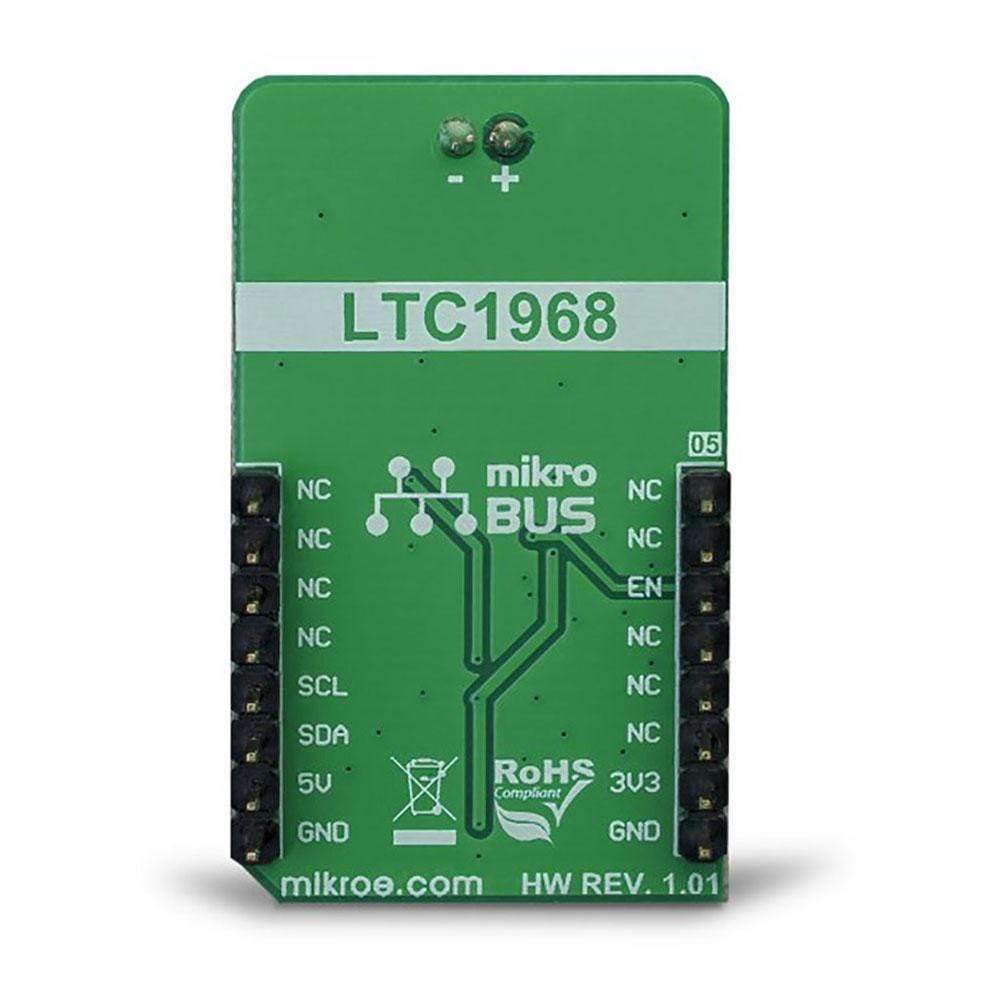
The RMS to DC Click Board™ is used to convert the RMS of the input signal into a DC voltage, with a value directly readable over the I2C interface. The Click Board™ is equipped with the LTC1968, an RMS-to-DC converter IC, which outputs an analog voltage depending on the RMS value of the input signal. The key feature of this IC is its very good linearity of the output voltage with respect to the RMS of the input signal. This is due to the innovative delta-sigma computational technique, used in this IC. Besides high linearity, this IC also features a high accuracy, high signal bandwidth, and good thermal stability. It can be used to accurately measure the RMS value of various alternating signals.
Downloads
Das RMS-zu-DC-Click-Board™ wird verwendet, um den Effektivwert des Eingangssignals in eine Gleichspannung umzuwandeln, deren Wert direkt über die I2C-Schnittstelle abgelesen werden kann. Das Click Board™ ist mit dem LTC1968 ausgestattet, einem RMS-zu-DC-Wandler-IC, der eine analoge Spannung abhängig vom Effektivwert des Eingangssignals ausgibt. Das Hauptmerkmal dieses IC ist seine sehr gute Linearität der Ausgangsspannung in Bezug auf den Effektivwert des Eingangssignals. Dies ist auf die innovative Delta-Sigma-Rechentechnik zurückzuführen, die in diesem IC verwendet wird. Neben hoher Linearität zeichnet sich dieser IC auch durch hohe Genauigkeit, hohe Signalbandbreite und gute thermische Stabilität aus. Er kann verwendet werden, um den Effektivwert verschiedener Wechselsignale genau zu messen.
| General Information | |
|---|---|
Part Number (SKU) |
MIKROE-3311
|
Manufacturer |
|
| Physical and Mechanical | |
Weight |
0.02 kg
|
| Other | |
EAN |
8606018714247
|
Frequently Asked Questions
Have a Question?
Be the first to ask a question about this.