


Mikroelektronika d.o.o.
RFID-Click-Platine
RFID-Click-Platine
SKU: MIKROE-1434
Verfügbarkeit für Abholungen konnte nicht geladen werden
Overview
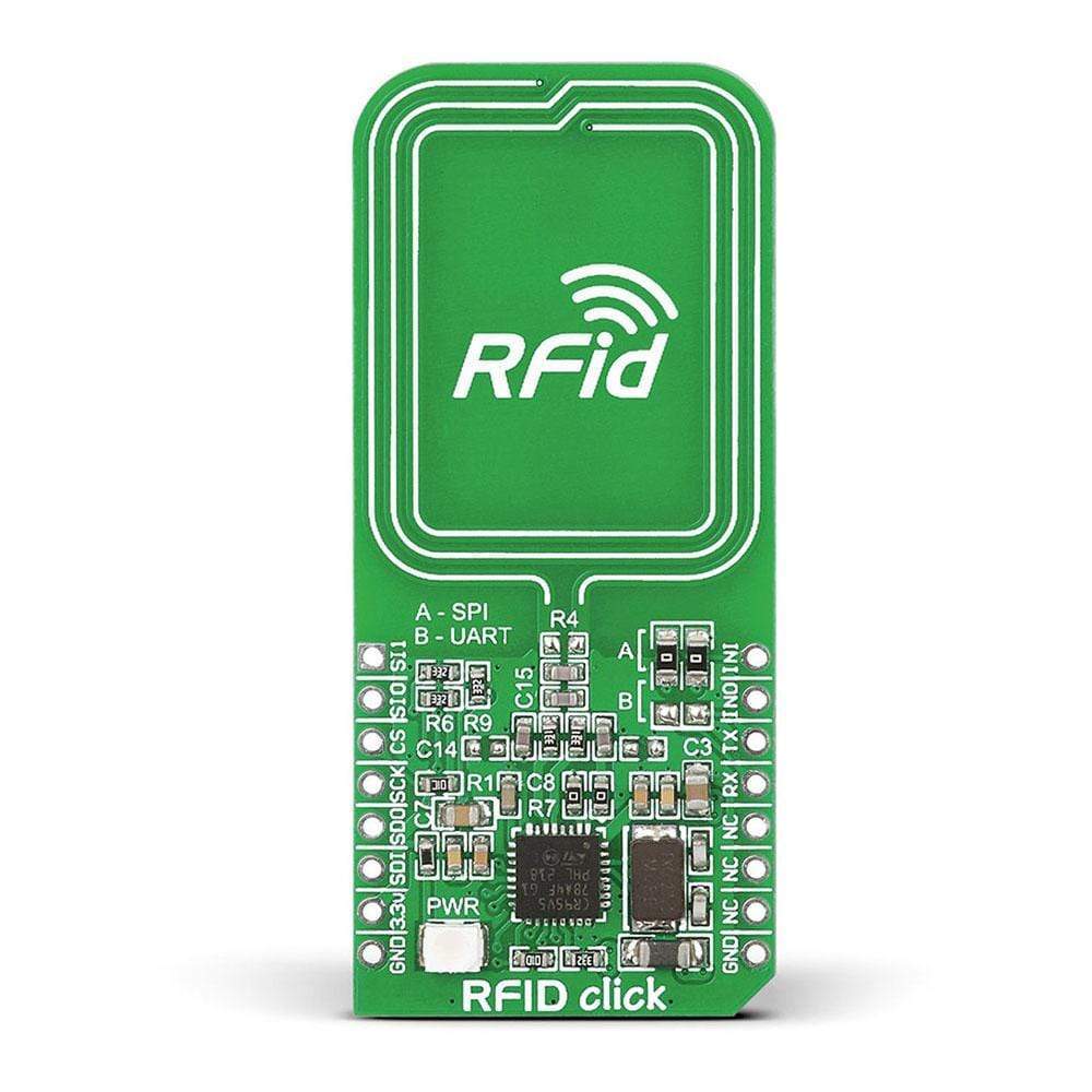
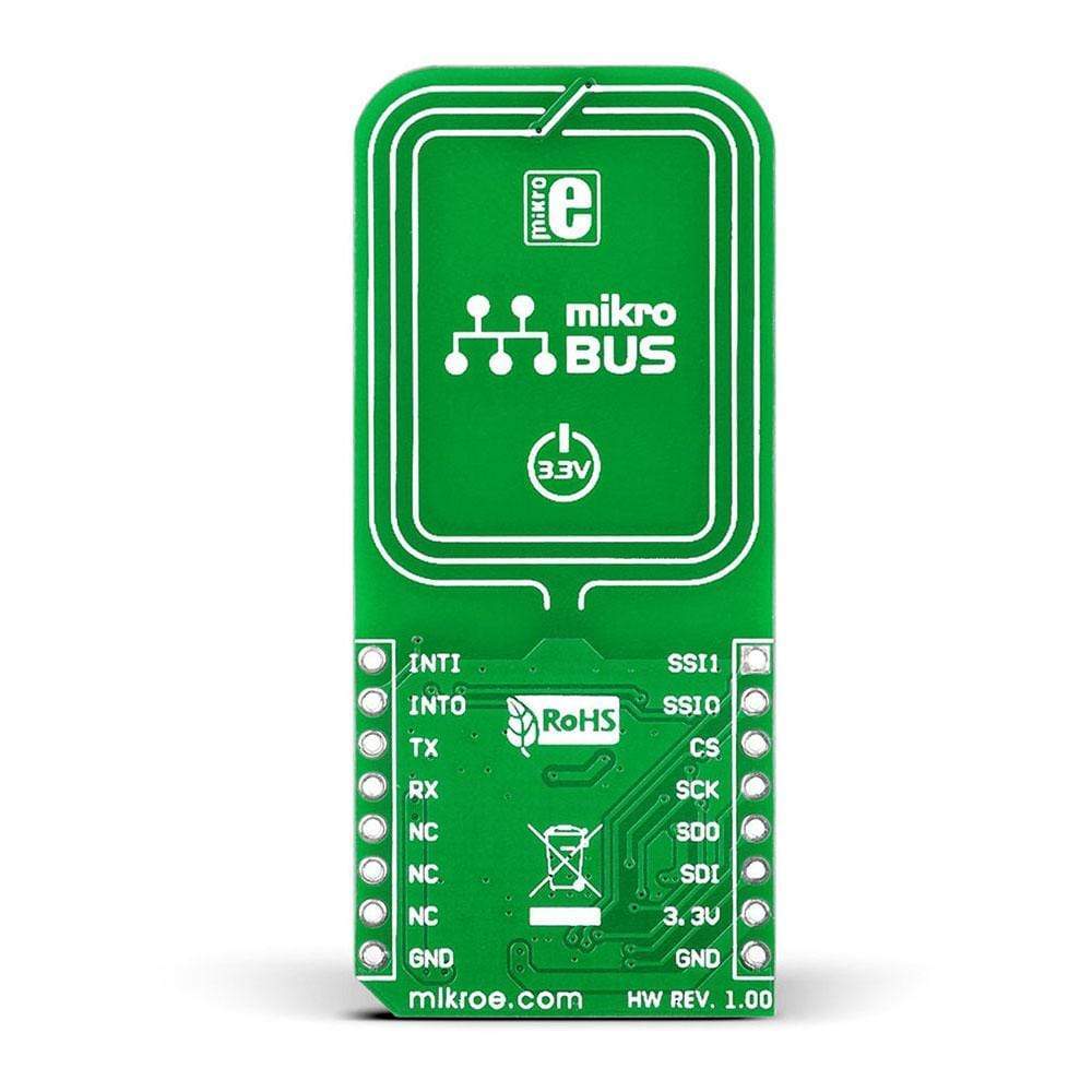
The RFID Click Board™ from MikroE offers an easy and compact solution to introduce RFid functionality to the design. This add-on board includes CR95HF, an integrated transceiver IC for contactless applications, as well as a PCB trace antenna. The CR95HF 13.56 MHz contactless transceiver can operate in reader/writer modes. It contains a dedicated internal frame controller and analogue front end (AFE) for RF communications. RFid Click Board™ communicates with the target board MCU through the MikroBUS UART (TX, RX), SPI (MISO, MOSI, SCK, CS) INT, RST, PWM and AN lines. The board supports a 3.3V power supply only. The power supply status is indicated by a green LED.
RFID Click Board™ supports ISO/IEC 14443 type A and B, ISO/IEC 15693 (single or double subcarrier) and ISO/IEC 18092 communication protocols. It also supports the detection, reading and writing of NFC Forum Type 1, 2, 3 and 4 tags. RFid Click Board™ can be used with 13.56 MHz RFid tags or identification cards. It is a perfect option for tracking and security systems that need RFID support.
Downloads
Das RFID Click Board™ von MikroE bietet eine einfache und kompakte Lösung, um RFID-Funktionalität in das Design einzuführen. Diese Zusatzplatine enthält CR95HF, einen integrierten Transceiver-IC für kontaktlose Anwendungen sowie eine PCB-Trace-Antenne. Der kontaktlose CR95HF-Transceiver mit 13,56 MHz kann im Lese-/Schreibmodus betrieben werden. Er enthält einen dedizierten internen Frame-Controller und ein analoges Frontend (AFE) für die HF-Kommunikation. Das RFID Click Board™ kommuniziert mit der Zielplatinen-MCU über die MikroBUS UART (TX, RX), SPI (MISO, MOSI, SCK, CS) INT-, RST-, PWM- und AN-Leitungen. Die Platine unterstützt nur eine 3,3-V-Stromversorgung. Der Stromversorgungsstatus wird durch eine grüne LED angezeigt.
RFID Click Board™ unterstützt die Kommunikationsprotokolle ISO/IEC 14443 Typ A und B, ISO/IEC 15693 (Einzel- oder Doppel-Subträger) und ISO/IEC 18092. Es unterstützt außerdem das Erkennen, Lesen und Schreiben von NFC Forum-Tags Typ 1, 2, 3 und 4. RFID Click Board™ kann mit 13,56 MHz RFID-Tags oder Identifikationskarten verwendet werden. Es ist eine perfekte Option für Tracking- und Sicherheitssysteme, die RFID-Unterstützung benötigen.
| General Information | |
|---|---|
Part Number (SKU) |
MIKROE-1434
|
Manufacturer |
|
| Physical and Mechanical | |
Weight |
0.035 kg
|
| Other | |
EAN |
8606015074610
|
Frequently Asked Questions
Have a Question?
Be the first to ask a question about this.