


Picotest
Picotest LM20143B VRM-Demoplatine V1.0
Picotest LM20143B VRM-Demoplatine V1.0
SKU: LM20143B
Verfügbarkeit für Abholungen konnte nicht geladen werden
Key Features
Overview
The Picotest LM20143 Point of Load Regulator Board is a cutting-edge demonstration platform for integrated synchronous buck regulation. This compact, self-contained unit showcases a 5V input and 1.2V/2.5A output configuration, leveraging emulated current mode control for straightforward flat impedance output creation.
Designed with accessibility in mind, the board features easily customisable 0805 chip size components, enabling engineers to experiment with various values. Powered via USB and equipped with an on-board resistive load, this demo board offers a complete testing environment for power regulation scenarios.
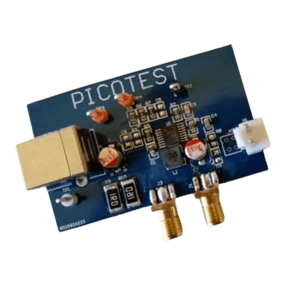
The LM20143 board is engineered for comprehensive analysis, incorporating provisions for Bode plot measurements. It includes a pre-installed injection resistor (R5) and dedicated test points (TP3 and TP4) for injection signal and measurement. SMA output connectors further enhance its versatility, facilitating connections for a wide range of measurements, including 2-port output impedance and step load tests.
Downloads
Die Schaltung ist ein integrierter synchroner Point-of-Load-Abwärtsregler mit einem 5-V-Eingang und einem 1,2-V/2,5-A-Ausgang. Das Gerät verwendet eine emulierte Strommodussteuerung, wodurch sich ganz einfach ein Ausgang mit flacher Impedanz erzeugen lässt. Leicht zugängliche Komponenten in Chipgröße 0805 erleichtern die Anpassung oder das Experimentieren mit verschiedenen Komponentenwerten. Dies ist eine vollständig in sich geschlossene Demoplatine mit USB-Eingangsstromversorgung und einer integrierten ohmschen Last.
Demonstrationsschaltungen
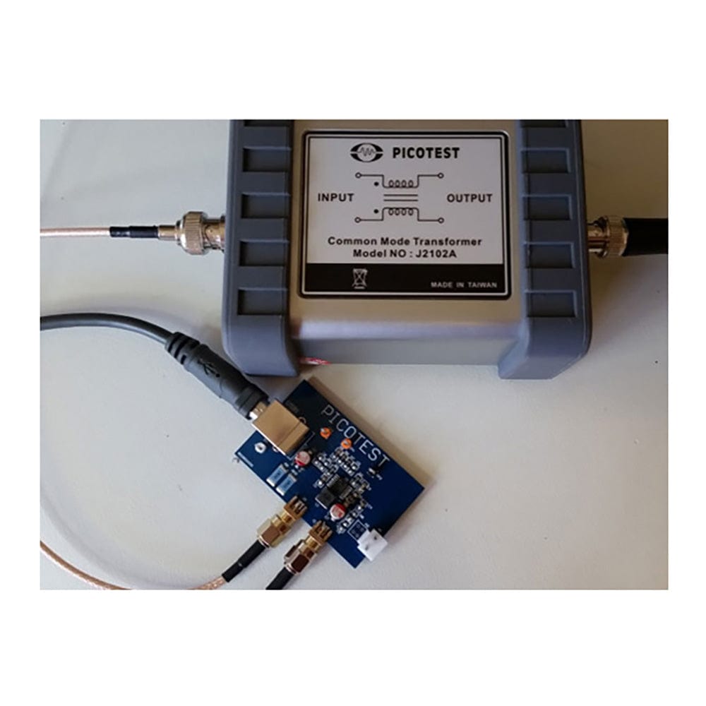
Die VRM-Demoplatine LM20143B ist für Bode-Diagrammmessungen konzipiert und verfügt über den Injektionswiderstand R5 sowie Testpunkte für das Injektionssignal und die Messung (TP3 und TP4). SMA-Ausgangsanschlüsse sind ebenfalls enthalten, um die Verbindungen für viele Messungen zu vereinfachen, darunter die Messung der 2-Port-Ausgangsimpedanz, die Stufenlast und andere gängige Messungen.
Die Stromversorgung der Platine erfolgt über USB, indem ein USB-Kabel mit einem Stecker vom Typ B an den Stromanschluss USB1 angeschlossen wird. (VORSICHT: R9 und R10 WERDEN HEISS – NICHT BERÜHREN)
| General Information | |
|---|---|
Part Number (SKU) |
LM20143B
|
Manufacturer |
|
| Other | |
EAN |
5055383624201
|
Frequently Asked Questions
Have a Question?
Be the first to ask a question about this.