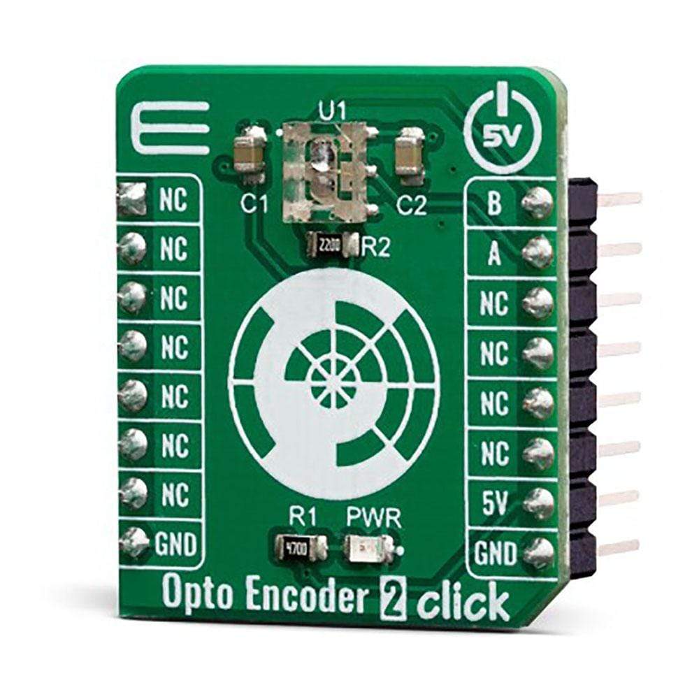
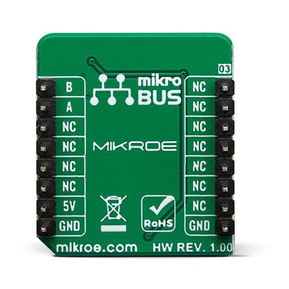
Opto Encoder 2 Click-Platine
Overview
Das Opto Encoder 2 Click Board™ ist ein lineares inkrementelles optisches Sensor-/Encoder-Click Board™, das zur Bewegungs- oder Rotationskodierung verwendet werden kann. Encoder dieser Art werden häufig für viele Anwendungen eingesetzt, bei denen es um die präzise Erkennung der Position, Geschwindigkeit oder des Rotationswinkels eines Objekts geht. Drehgeber werden häufig für verschiedene Arten von Steuerungen auf vielen verschiedenen Geräten verwendet. Ob Drehgeber-Knopfsteuerung oder Winkelgeber auf einer Motorwelle, das Prinzip ist dasselbe – es enthält einen optischen Sensor, genau wie den auf dem Opto Encoder 2 Click Board™ .
This Opto Encoder 2 Click Board™ features a very small optical encoder employing reflective technology for motion control purposes. The encoder houses an LED light source and a photo-detecting circuitry in a single package. It can be used as an optical sensor in automotive applications, motion, speed, and direction sensor, for precise motor shaft positioning applications, knob encoder applications, and similar applications, where dual channel optical sensing can be utilized.
How Does The Opto Encoder 2 Click Board™ Work?
The optical sensor used on the Opto Encoder 2 Click Board™ is the AEDR-8300, reflective Surface Mount Optical Encoder from Avago Technologies. This sensor combines an emitter and a detector in a single surface mount leadless package. the AEDR-8300 consists of three major components: a light emitting diode (LED) light source, a detector IC consisting photodiodes and lens to focus light beam from the emitter as well as light falling on the detector. The operation of the encoder is based on the principle of optics where the detector photodiodes sense the absence and presence of light. In this case, the rotary/linear motion of an object being monitored is converted to equivalent light pattern via the use of codewheel/codestrip.
The Opto Encoder 2 Click Board™ offers options of either single channel or two-channel quadrature digital outputs. Being TTL compatible, the outputs of the AEDR-8300 series can be interfaced directly with MCU. Hence the Opto Encoder 2 Click Board™ provides great design-in flexibility and easy integration into existing systems. A and B pins are routed to the routed to the mikroBUS PWM and INT pins, thus providing the quadrature digital signal.
Signal encoding itself is done by the host MCU. Having two optical sensing channels, Opto Encoder 2 Click Board™ has the ability of both speed and direction encoding. The most common usage is encoding of the step motor position: a cylinder with slits is physically mounted above the sensor so that the LED can illuminate the photodiodes only when light hits the reflective surface of the codewheel. By rotating this cylinder, the light beam will be blocked periodically. The single sensor output will be a pulse train, while the cylinder is rotating. Having two photo sensors physically distanced by a small amount, allows the pulse signal of the first sensor to be either delayed or expedited with respect to the pulse on the second sensor, depending on the rotational direction.
Since the sensors recommended operating voltage is 5V, the Opto Encoder 2 Click Board™ uses the 5V rail for power supply. The other pins it utilizes are the, before mentioned, Interrupt and PWM pins on mikroBUS socket. This Click Board™ also has a Power LED indicator.
The Opto Encoder 2 Click Board™ is designed to be operated only with 5V logic level. A proper logic voltage level conversion should be performed before the Click Board™ is used with MCUs with logic levels of 3.3V.
SPECIFICATIONS
Type | Optical |
Applications | Automotive optical sensors, accurate position sensor for encoder, sensor for motion, speed, and direction, etc. |
On-board modules | Reflective Surface Mount Optical Encoder from Avago Technologies |
Key Features | The Opto Encoder 2 Click Board™ features a precise detection of the position, speed, or rotational angle of an object. It is able to detect the direction of the movement since it features two photo-sensing elements. |
Interface | GPIO |
Compatibility | mikroBUS |
Click Board™ size | S (28.6 x 25.4 mm) |
Input Voltage | 5V |
PINOUT DIAGRAM
This table shows how the pinout of the Opto Encoder 2 Click Board™
s | Pin | Pin | Notes | ||||
---|---|---|---|---|---|---|---|
NC | 1 | AN | PWM | 16 | B | Output B | |
NC | 2 | RST | INT | 15 | A | Output A | |
NC | 3 | CS | RX | 14 | NC | ||
NC | 4 | SCK | TX | 13 | NC | ||
NC | 5 | MISO | SCL | 12 | NC | ||
NC | 6 | MOSI | SDA | 11 | NC | ||
NC | 7 | +3.3V | 5V | 10 | +5V | Power Supply | |
Ground | GND | 8 | GND | GND | 9 | GND | Ground |
OPTO ENCODER 2 Click Board™ SPECIFICATIONS
Description | Min | Typ | Max | Unit |
---|---|---|---|---|
Supply Voltage | 4.5 | 5 | 5.5 | V |
LED Current | 13 | 15 | 18 | µs |
Count Frequency | - | - | 30 | kHZ |
Resolution | - | 75 | - | LPI |
ONBOARD SETTINGS AND INDICATORS
Label | Name | Default | Description |
---|---|---|---|
LD1 | PWR | - | Power LED Indicator |
We provide a library for the Opto Encoder 2 Click Board™ on our LibStock page, as well as a demo application (example), developed using MikroElektronika compilers. The demo can run on all the main MikroElektronika development boards.
Library Description
Library contains functions for getting INT(Channel A) and PWM (Channel B) pin states Library contains function for incrementing/decrementing encoder position Library contains function for resetting encoder position counter to 0(zero) Library contains function for getting current encoder position
Key Functions
int32_t optoencoder2_getPosition(void)
- returns current encoder position.void optoencoder2_zeroCounter(void)
- resets encoder counter to 0(zero).uint8_t optoencoder2_isr( uint8_t n_cycles )
- checks for rising edge on Channel A (INT pin), within specified number of cycles (n_cycles), and increments or decrements encoder position.
Example Description
The application is composed of three sections :
- System Initialization - Initializes LOG, initializes PWM and INT pins.
- Application Initialization - Initializes GPIO driver and resets encoder counter to 0(zero) .
- Application Task - If encoder is moving - increments or decrements encoder position on every rising edge on Channel A (INT pin) and logs encoder position .
void applicationTask( ) { stop_flag = optoencoder2_isr(100); encoderPosition = optoencoder2_getPosition( ); if (stop_flag == 0) { LongToStr( encoderPosition, text ); mikroBUS_logWrite( "> pos : ", _LOG_TEXT ); mikroBUS_logWrite( text, _LOG_LINE ); } }
The full application code, and ready to use projects can be found on our LibStock page.
Other mikroE Libraries used in the example:
- UART
- Conversions
Additional Notes and Information
Depending on the development board you are using, you may need a USB UART Click Board™, USB UART 2 Click Board™ or RS232 Click Board™ to connect to your PC, for development systems with no UART to USB interface available on the board. The terminal available in all Mikroelektronika compilers, or any other terminal application of your choice, can be used to read the message.
MIKROSDK
The Opto Encoder 2 Click Board™ is supported with mikroSDK - MikroElektronika Software Development Kit. To ensure proper operation of mikroSDK compliant Click Board™ demo applications, mikroSDK should be downloaded from the LibStock and installed for the compiler you are using.
Frequently Asked Questions
Have a Question?
Be the first to ask a question about this.