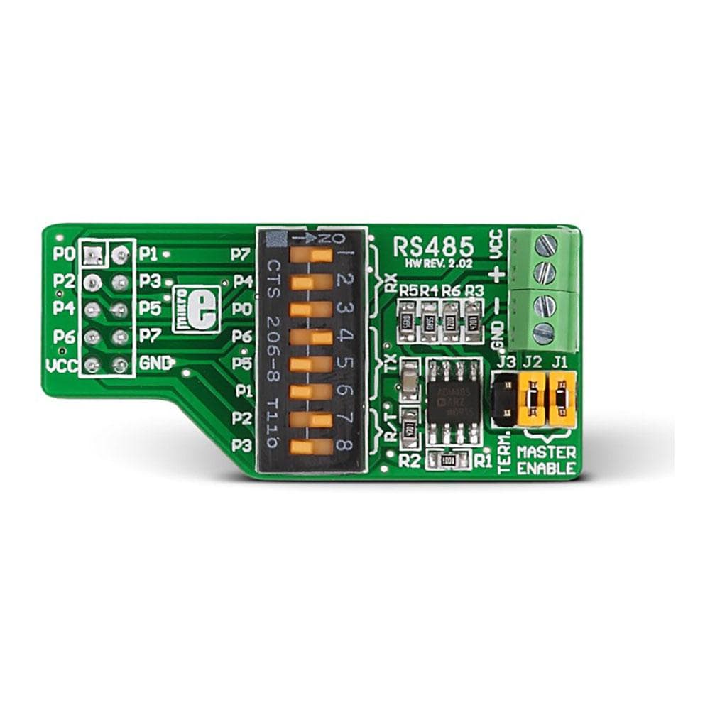
Overview
Designed for RS-485 communication, the RS-485 Interface Board is a perfect option for use in electrically noisy environments on long distances (up to 1200 metres). The board features an integrated ADM485 differential line transceiver that can be used for high-speed bi-directional communications in a multipoint design. Compliant with EIA standards RS-485 and RS-422, this differential transceiver provides balanced data transmission lines. The ADM485 module aboard the RS485 additional board has a differential line driver and a differential line receiver. It is designed to operate using a 5V power supply only. Use of voltage translators is advised when using the board with 3.3V development systems.
The RS-485 Interface Board is an ideal choice for low power RS485 systems, DTE/DCE interfaces, packet switching, Local Area Networks (LANs), data concentration, data multiplexers, Integrated Services Digital Network (ISDN), and many more.
Downloads
Die für die RS-485-Kommunikation konzipierte RS-485 -Schnittstellenkarte ist eine perfekte Option für den Einsatz in elektrisch lauten Umgebungen über lange Distanzen (bis zu 1200 Meter). Die Karte verfügt über einen integrierten ADM485-Differentialleitungstransceiver, der für bidirektionale Hochgeschwindigkeitskommunikation in einem Mehrpunktdesign verwendet werden kann. Dieser Differentialtransceiver entspricht den EIA-Standards RS-485 und RS-422 und bietet symmetrische Datenübertragungsleitungen. Das ADM485-Modul an Bord der RS485-Zusatzkarte verfügt über einen Differentialleitungstreiber und einen Differentialleitungsempfänger. Es ist nur für den Betrieb mit einer 5-V-Stromversorgung ausgelegt. Bei Verwendung der Karte mit 3,3-V-Entwicklungssystemen wird die Verwendung von Spannungswandlern empfohlen.
Die RS-485 - Schnittstellenkarte ist die ideale Wahl für RS485-Systeme mit geringem Stromverbrauch, DTE/DCE-Schnittstellen, Paketvermittlung, lokale Netzwerke (LANs), Datenkonzentration, Datenmultiplexer, Integrated Services Digital Network (ISDN) und vieles mehr.
| General Information | |
|---|---|
Part Number (SKU) |
MIKROE-66
|
Manufacturer |
|
| Physical and Mechanical | |
Weight |
0.01 kg
|
| Other | |
Warranty |
|
HS Code Customs Tariff code
|
|
EAN |
8606015072036
|
Frequently Asked Questions
Have a Question?
Be the first to ask a question about this.

