Key Features
Overview
Introducing the RS485 7 Click Board™: Revolutionize Your Industrial Communication
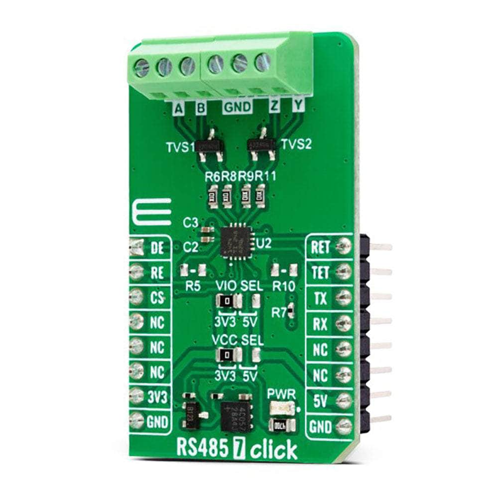
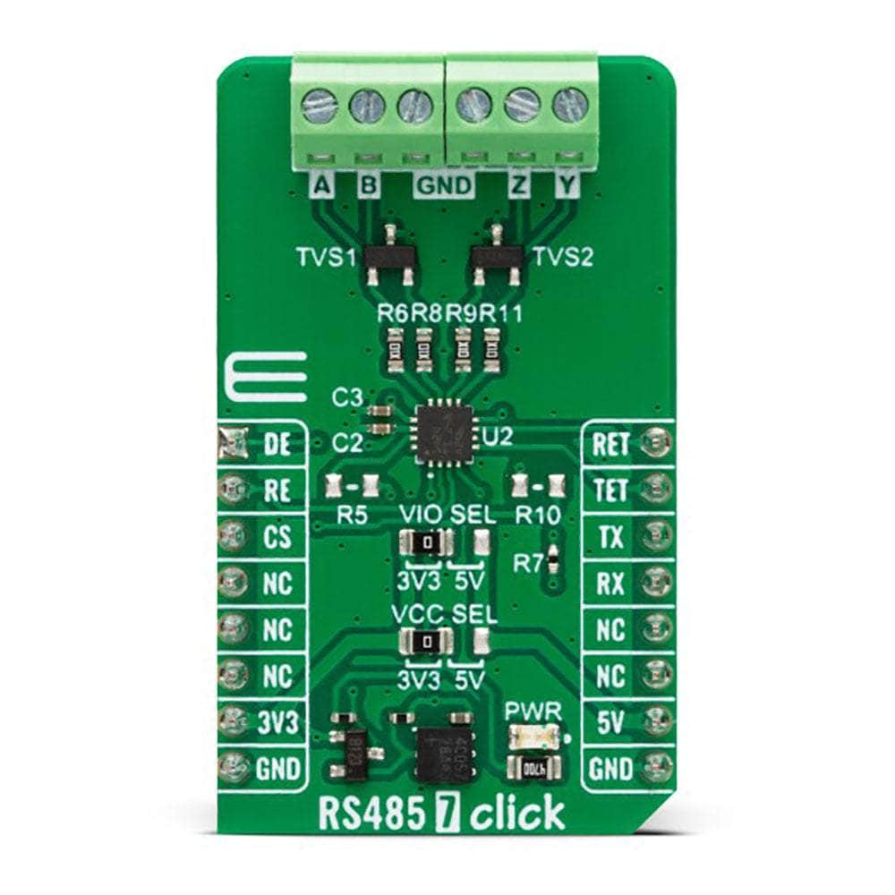
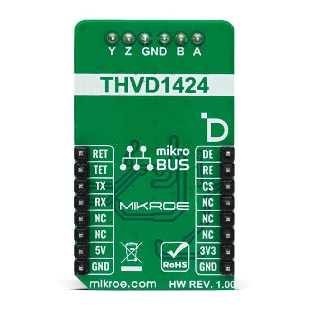
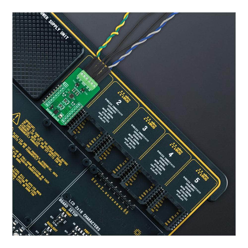
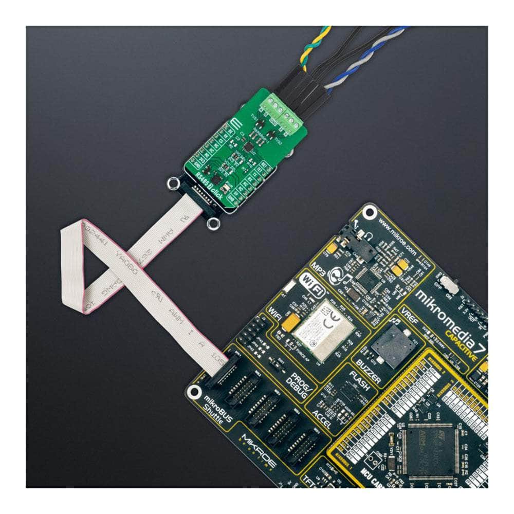
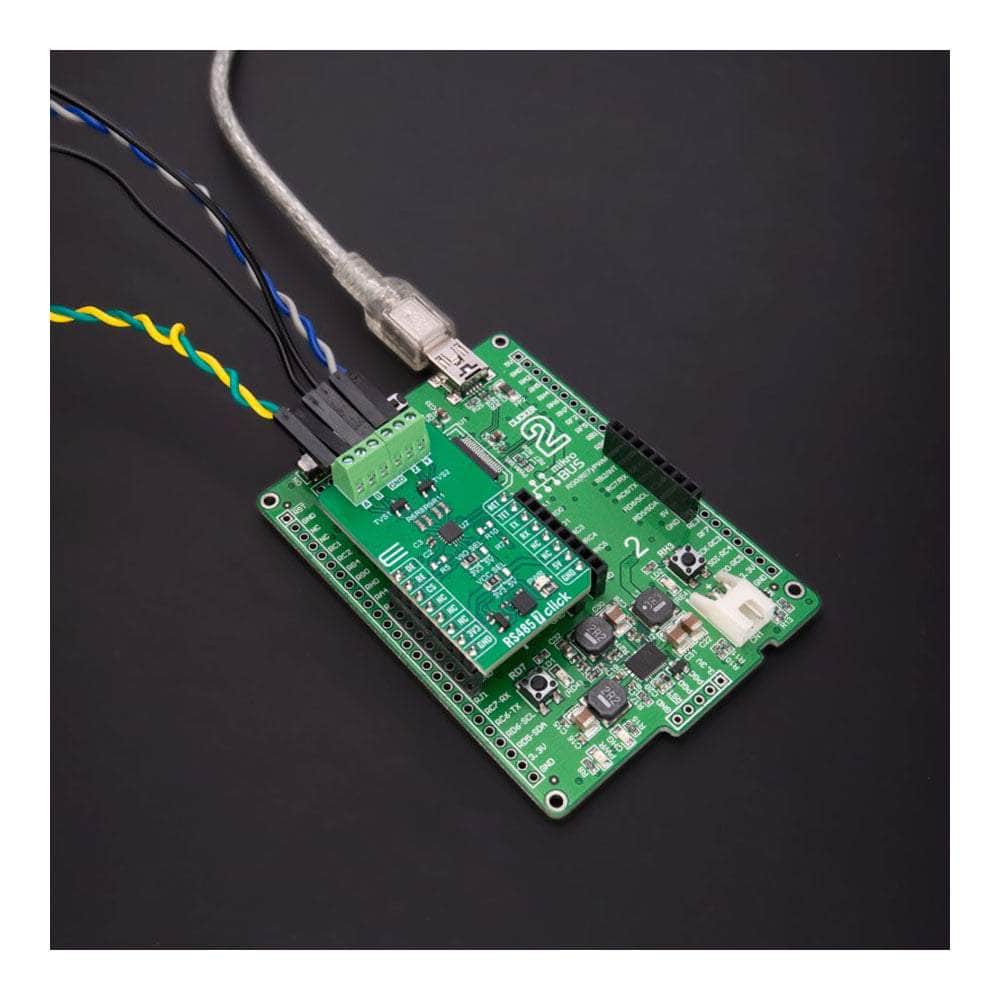
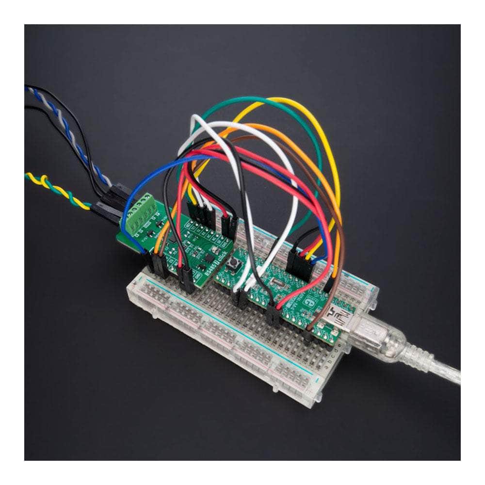
Experience the future of industrial communication with the RS485 7 Click Board™, a sleek and compact add-on board designed to transform your RS485 network communication. Powered by Texas Instruments' THVD1424, a state-of-the-art full duplex RS485 transceiver, this game-changing device promises unparalleled data rate customization.
Unlock the Power of Pin-Controlled Features
Discover the endless possibilities of THVD1424's various pin-controlled features, such as an integrated 120Ω termination resistor, cutting-edge slew rate control, and seamless switching between half and full duplex mode. With a high immunity to IEC Contact Discharge ESD events, your bus pins are fully protected without any additional system-level components.
Experience Low Power Consumption and Hot Plug-In Capability
Save on energy with the THVD1424's impressively low power consumption and enjoy the convenience of glitch-free power-up/power-down functionality. Hot plug-in capability means you can effortlessly integrate the RS485 7 Click Board™ into your existing setup, making it perfect for industrial and multi-point applications over extended cable runs.
Effortless Software Development with mikroSDK
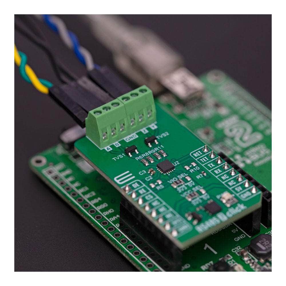
Maximize your efficiency with the RS485 7 Click Board™, supported by a mikroSDK-compliant library that includes user-friendly functions to simplify software development. Fully tested and ready for use, this Click board™ integrates seamlessly with any system equipped with the mikroBUS™ socket, allowing you to focus on what matters most—your project.
Upgrade Your Communication System Today
Don't let outdated technology hold you back. Invest in the RS485 7 Click Board™ and witness the remarkable difference it brings to your industrial communication network. Get ready to revolutionize your workflow and elevate your projects to new heights!
Downloads
Einführung des RS485 7 Click Board™: Revolutionieren Sie Ihre industrielle Kommunikation
Erleben Sie die Zukunft der industriellen Kommunikation mit dem RS485 7 Click Board™, einer schlanken und kompakten Zusatzplatine, die Ihre RS485-Netzwerkkommunikation transformieren soll. Angetrieben vom THVD1424 von Texas Instruments, einem hochmodernen Vollduplex-RS485-Transceiver, verspricht dieses bahnbrechende Gerät eine beispiellose Anpassung der Datenrate.
Nutzen Sie die Leistungsfähigkeit von Pin-gesteuerten Funktionen
Entdecken Sie die endlosen Möglichkeiten der verschiedenen pingesteuerten Funktionen des THVD1424, wie z. B. einen integrierten 120-Ω-Abschlusswiderstand, modernste Slew-Rate-Steuerung und nahtloses Umschalten zwischen Halb- und Vollduplexmodus. Dank der hohen Immunität gegen IEC-Kontaktentladungen (ESD) sind Ihre Buspins vollständig geschützt, ohne dass zusätzliche Komponenten auf Systemebene erforderlich sind.
Erleben Sie niedrigen Stromverbrauch und Hot-Plug-In-Fähigkeit
Sparen Sie Energie mit dem beeindruckend niedrigen Stromverbrauch des THVD1424 und genießen Sie den Komfort einer störungsfreien Ein-/Ausschaltfunktion. Dank der Hot-Plug-in-Funktion können Sie das RS485 7 Click Board™ mühelos in Ihr vorhandenes Setup integrieren, was es perfekt für industrielle und Mehrpunktanwendungen über längere Kabelstrecken macht.
Mühelose Softwareentwicklung mit mikroSDK
Maximieren Sie Ihre Effizienz mit dem RS485 7 Click Board™, unterstützt durch eine mikroSDK-kompatible Bibliothek, die benutzerfreundliche Funktionen zur Vereinfachung der Softwareentwicklung enthält. Dieses vollständig getestete und einsatzbereite Click Board™ lässt sich nahtlos in jedes System integrieren, das mit der mikroBUS™-Buchse ausgestattet ist, sodass Sie sich auf das Wesentliche konzentrieren können – Ihr Projekt.
Rüsten Sie Ihr Kommunikationssystem noch heute auf
Lassen Sie sich nicht von veralteter Technologie zurückhalten. Investieren Sie in das RS485 7 Click Board™ und erleben Sie den bemerkenswerten Unterschied, den es für Ihr industrielles Kommunikationsnetzwerk bringt. Machen Sie sich bereit, Ihren Arbeitsablauf zu revolutionieren und Ihre Projekte auf ein neues Niveau zu heben!
| General Information | |
|---|---|
Part Number (SKU) |
MIKROE-5659
|
Manufacturer |
|
| Physical and Mechanical | |
Weight |
0.02 kg
|
| Other | |
Country of Origin |
|
HS Code Customs Tariff code
|
|
EAN |
8606027384950
|
Warranty |
|
Frequently Asked Questions
Have a Question?
-
How can I benefit from using the RS485 7 Click Board™?
By utilizing the RS485 7 Click Board™, you unlock a world of possibilities. You can achieve efficient and reliable communication over RS485 networks, ensuring seamless data transfer and robust system performance. With its exceptional features, immunity to ESD events, and low power consumption, this board provides a highly efficient solution for your communication needs.
-
What applications is the RS485 7 Click Board™ suitable for?
The RS485 7 Click Board™ is highly versatile and suitable for a wide range of applications. Its industrial-grade capabilities make it ideal for industrial automation, control systems, sensor networks, building automation, and many other industrial scenarios. It also excels in multi-point applications over long cable runs, making it a valuable asset in complex setups.
-
Is the RS485 7 Click Board™ easy to use?
Absolutely! The RS485 7 Click Board™ comes as a fully tested and pre-assembled product, ready to be integrated into any system equipped with the widely adopted mikroBUS™ socket. With its user-friendly design and intuitive interface, you can start using it right out of the box. The mikroSDK-compliant library provides functions that streamline software development, making it even easier to incorporate this board into your projects.
-
What are the benefits of using the RS485 7 Click Board™?
By utilizing the RS485 7 Click Board™, you gain access to a world of advantages. This board is specifically designed for industrial and multi-point applications over long cable runs, making it perfect for various scenarios. Its compact size allows for easy integration into your existing systems. The RS485 7 Click Board™ ensures reliable and robust communication, guaranteeing seamless data transfer across your network. It simplifies software development through the mikroSDK-compliant library, enabling hassle-free implementation.
-
What features does the RS485 7 Click Board™ offer?
The RS485 7 Click Board™ is packed with remarkable features. The THVD1424 transceiver provides pin-controlled capabilities such as an on-chip 120Ω termination resistor, slew rate control, and the ability to switch between half and full duplex mode. It also boasts exceptional immunity to IEC Contact Discharge ESD events, eliminating the need for additional protection components in your system. Moreover, the chip's low power consumption and glitch-free power-up/power-down functionality enable hot plug-in capability.

