


Mikroelektronika d.o.o.
DIGI POT 12 Click-Platine
DIGI POT 12 Click-Platine
Verfügbarkeit für Abholungen konnte nicht geladen werden
Key Features:
- Zweikanalig, Auflösung von 256 Positionen, 10 kΩ Nennwiderstand, I2C-kompatible Schnittstelle, nichtflüchtiger Speicher speichert Wischereinstellungen, 50 Jahre typische Datenspeicherung und mehr
- Basierend auf dem AD5142A - digitales Potentiometer von Analog Devices
- Kann für die Entwicklung von mechanischen Potentiometer-Ersatzteilen, Spannungs-Strom-Umwandlungen, Verstärkungs- und Offset-Anpassungen und viele andere Anwendungen verwendet werden
- mikroBUS: I2C-Schnittstelle
Das DIGI POT 12 Click Board™ ist eine innovative Zusatzplatine, die die Potentiometersteuerung revolutionieren soll. Mit seiner kompakten Größe und den erweiterten Funktionen ist diese Platine ein Muss für jeden Elektronik-Enthusiasten oder Profi.
Entfesseln Sie die Leistung der digitalen Potentiometer-Technologie
Das Herzstück des DIGI POT 12 Click Board™ ist der hochmoderne AD5142A von Analog Devices. Dieses nichtflüchtige digitale Potentiometer mit zwei Kanälen und 256 Positionen bietet beispiellose Präzision und Leistung. Diese Platine garantiert außergewöhnliche Zuverlässigkeit und Genauigkeit mit einem beeindruckenden End-to-End-Widerstand von 10 kΩ und einem Schleifwiderstand von nur 40 Ω.
Vielseitigkeit auf Knopfdruck
Mit dem DIGI POT 12 Click Board™ haben Sie Zugriff auf zwei digital gesteuerte Potentiometer, die sich ganz einfach über die I2C-Schnittstelle einstellen lassen. Egal, ob Sie ein Potentiometer oder lineare Verstärkungsmodi benötigen, diese Platine bietet alles. Verabschieden Sie sich von mechanischen Potentiometern und nutzen Sie eine effizientere und präzisere Steuerungslösung.
Unendliche Möglichkeiten für Ihre Projekte
Schöpfen Sie das volle Potenzial Ihrer elektronischen Projekte mit dem DIGI POT 12 Click Board™ aus. Dieses vielseitige Board eignet sich perfekt für die Entwicklung einer breiten Palette von Anwendungen, darunter:
Austausch mechanischer Potentiometer, Umwandlung von Spannung in Strom, Verstärkungs- und Offset-Anpassungen und vieles mehr!Erleben Sie unübertroffene Kontrolle und Flexibilität mit dem DIGI POT 12 Click Board™.
Optimierte Softwareentwicklung
Die Entwicklung von Software für das DIGI POT 12 Click Board™ war noch nie so einfach. Dank der mikroSDK-kompatiblen Bibliothek haben Sie Zugriff auf einen umfassenden Satz von Funktionen, die den Entwicklungsprozess vereinfachen. Verabschieden Sie sich von komplexer Codierung und begrüßen Sie effiziente Softwareentwicklung.
Bereit zur sofortigen Integration
Das DIGI POT 12 Click Board™ wird vollständig getestet geliefert und ist bereit zur Integration in Ihr System. Ausgestattet mit der beliebten mikroBUS™-Buchse lässt sich dieses Board problemlos in Ihr vorhandenes Setup einbinden. Einfach einstecken und mit dem DIGI POT 12 Click Board™ können Sie Ihre Projekte auf ein neues Niveau heben.
Rüsten Sie Ihre Potentiometersteuerung noch heute mit dem DIGI POT 12 Click Board™ auf. Bestellen Sie jetzt und erleben Sie die Zukunft der Präzisionssteuerung.


How Does The DIGI POT 12 Click Board™ Work?
The DIGI POT 12 Click Board™ is based on the AD5142A, a dual-channel, 256-position nonvolatile digital potentiometer from Analog Devices. The RDAC register contents determine the resistor wiper position, that act as a scratchpad register, allowing unlimited changes of resistance settings. The scratchpad register can be programmed with any position setting using the standard I2C interface by loading the 16-bit data word. The nominal resistance of the RDAC between terminals A and terminals B (RAB) is 10KΩ with 8-bit RDAC latch data decoded to select one of the 256 possible wiper settings. When a desired position is found, this value can be stored in the onboard EEPROM memory; thus, the wiper position is always restored for subsequent power-ups. The EEPROM data can be read back, written independently, and protected by software.
This Click board™ communicates with MCU through a standard 2-Wire I2C interface and operates at Standard (100KHz) and Fast (400KHz) data transfer modes. The I2C address can be selected via the ADDR SEL jumpers with 0 selected by default. There is an RST pin for resetting the digital potentiometers RDAC registers from EEPROM, with active LOW logic. In addition, this Click board™ comes with the INDEP SEL jumper that allows you to choose between the potentiometer and the linear gain setting mode, with the potentiometer mode set by default (0).
The linear gain setting mode of operation can control the potentiometer as two independent rheostats connected at a single point. Once the jumper is set, it can not be disabled by software. In addition, there is a burst mode in which multiple data bytes can be sent to the host MCU. The Shutdown mode places the RDAC in a zero power consumption while the data in EEPROM remains. There is no polarity constraint between the B, W, and A on both terminals, but they can not be higher than the VCC (5V maximum) nor lower than the VSS (0V).
The DIGI POT 12 Click Board™ can operate with either 3.3V or 5V logic voltage levels selected via the VCC SEL jumper. This way, both 3.3V and 5V capable MCUs can use the communication lines properly. However, the Click board™ comes equipped with a library containing easy-to-use functions and an example code that can be used, as a reference, for further development.
SPECIFICATIONS
| Type | Digital potentiometer |
| Applications | It can be used for the development of mechanical potentiometer replacements, voltage-to-current conversions, gain and offset adjustment, and many other applications |
| On-board modules | AD5142A - digital potentiometer from Analog Devices |
| Key Features | Dual-channel, 256-position resolution, 10kΩ nominal resistance, I2C-compatible interface, nonvolatile memory stores wiper settings, 50 years of typical data retention, and more |
| Interface | I2C |
| Compatibility | mikroBUS |
| Click board size | M (42.9 x 25.4 mm) |
| Input Voltage | 3.3V or 5V |
PINOUT DIAGRAM
This table shows how the pinout of the DIGI POT 12 Click Board™ corresponds to the pinout on the mikroBUS™ socket (the latter shown in the two middle columns).
| Notes | Pin | Pin | Notes | ||||
|---|---|---|---|---|---|---|---|
| NC | 1 | AN | PWM | 16 | NC | ||
| Reset | RST | 2 | RST | INT | 15 | NC | |
| NC | 3 | CS | RX | 14 | NC | ||
| NC | 4 | SCK | TX | 13 | NC | ||
| NC | 5 | MISO | SCL | 12 | SCL | I2C Clock | |
| NC | 6 | MOSI | SDA | 11 | SDA | I2C Data | |
| Power Supply | 3.3V | 7 | 3.3V | 5V | 10 | 5V | Power Supply |
| Ground | GND | 8 | GND | GND | 9 | GND | Ground |
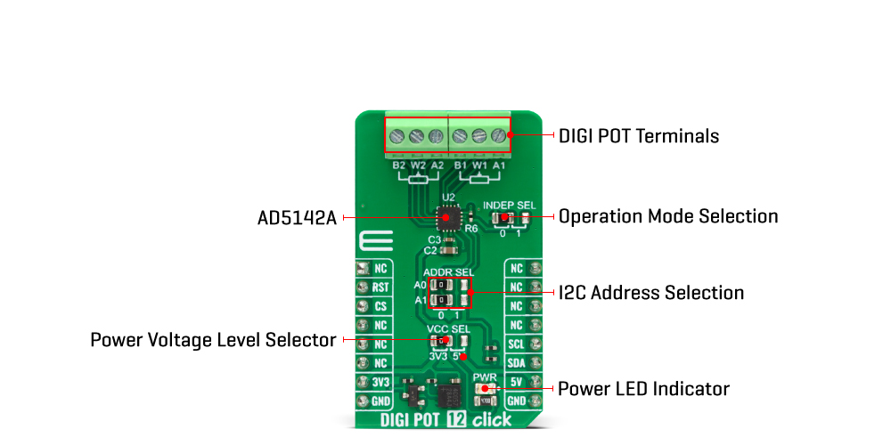
ONBOARD SETTINGS AND INDICATORS
| Label | Name | Default | Description |
|---|---|---|---|
| LD1 | PWR | - | Power LED Indicator |
| JP1 | VCC SEL | Left | Power/Logic Level Voltage Selection 3V3/5V: Left position 3V3, Right position 5V |
| JP2 | INDEP SEL | Left | Operating Mode Selection 0/1: Left position 0, Right position 1 |
| JP3-JP4 | ADDR SEL | Left | I2C Address Selection 0/1: Left position 0, Right position 1 |
DIGI POT 12 CLICK ELECTRICAL SPECIFICATIONS
| Description | Min | Typ | Max | Unit |
|---|---|---|---|---|
| Supply Voltage | 3.3 | - | 5 | V |
| Nominal Resistance | - | 10 | - | kΩ |
| Number of Taps | - | - | 256 | - |
| Resolution | 8 | - | - | bits |
Software Support
We provide a library for the DIGI POT 12 Click Board™ as well as a demo application (example), developed using MIKROE compilers. The demo can run on all the main MIKROE development boards.
The package can be downloaded/installed directly from NECTO Studio The package Manager (recommended), downloaded from our LibStock™ or found on MikroE Github account.
Library Description
This library contains API for the DIGI POT 12 Click Board™ driver.
Key functions
-
digipot12_set_resistanceDIGI POT 12 set the resistance function. -
digipot12_get_resistanceDIGI POT 12 get the resistance function.
Example Description
This library contains API for the DIGI POT 12 Click Board™ driver. The demo application uses a digital potentiometer to change the resistance values of both channels.
void application_task ( void )
 {
 static float res_kohm;
 for ( uint8_t n_cnt = DIGIPOT12_RES_0_KOHM; n_cnt <= DIGIPOT12_RES_10_KOHM; n_cnt++ )
 {
 if ( DIGIPOT12_OK == digipot12_set_resistance( &digipot12, DIGIPOT12_WIPER_SEL_1, ( float ) n_cnt ) )
 {
 if ( DIGIPOT12_OK == digipot12_get_resistance( &digipot12, DIGIPOT12_WIPER_SEL_1, &res_kohm ) )
 {
 log_printf( &logger, " Rwb1 : %.2f kOhmrn", res_kohm );
 Delay_ms( 100 );
 }
 }
 if ( DIGIPOT12_OK == digipot12_set_resistance( &digipot12, DIGIPOT12_WIPER_SEL_2, ( float ) ( DIGIPOT12_RES_10_KOHM - n_cnt ) ) )
 {
 if ( DIGIPOT12_OK == digipot12_get_resistance( &digipot12, DIGIPOT12_WIPER_SEL_2, &res_kohm ) )
 {
 log_printf( &logger, " Rwb2 : %.2f kOhmrn", res_kohm );
 Delay_ms( 100 );
 }
 }
 log_printf( &logger, " ----------------------------rn" );
 Delay_ms( 5000 );
 }
 }
The full application code, and ready to use projects can be installed directly from NECTO Studio The package Manager (recommended), downloaded from our LibStock™ or found on MikroE Github account.
Other MikroE Libraries used in the example:
- MikroSDK.Board
- MikroSDK.Log
- Click.DIGIPOT12
Additional Notes and Information
Depending on the development board you are using, you may need USB UART Click Board™, USB UART 2 Click or RS232 Click to connect to your PC, for development systems with no UART to USB interface available on the board. UART terminal is available in all MIKROE compilers.
MIKROSDK
The DIGI POT 12 Click Board™ is supported with mikroSDK - MIKROE Software Development Kit, which needs to be downloaded from the LibStock and installed for the compiler you are using to ensure proper operation of mikroSDK compliant Click board™ demo applications.
DIGI POT 12 Click-Platine
Frequently Asked Questions
Have a Question?
Be the first to ask a question about this.