


Mikroelektronika d.o.o.
Solarenergie 2 Click Board
Solarenergie 2 Click Board
Verfügbarkeit für Abholungen konnte nicht geladen werden
Key Features:
- Verschiedene DC-Erntequellen, darunter thermoelektrische Generatoren (TEG) oder Photovoltaik (Solar), Quellen im μW- bis mW-Bereich, flexibler Betrieb mit Primärzellenbatterien, Goldkondensatoren und Superkondensatoren, Hilfsspannungsausgang, programmierbare Schwellenwerte, integriertes EEPROM und mehr
- Basierend auf dem EM8500 - Power-Management-Controller mit Energy-Harvesting-Schnittstelle von EM Microelectronic
- Kann zur Stromversorgung von drahtlosen Sensornetzwerken, Umweltüberwachungsgeräten, tragbaren und am Körper tragbaren Geräten zur Gesundheitsüberwachung, batteriebetriebenen Plattformen und ähnlichen stromsparenden, autarken Geräten verwendet werden.
- mikroBUS: I2C-Schnittstelle
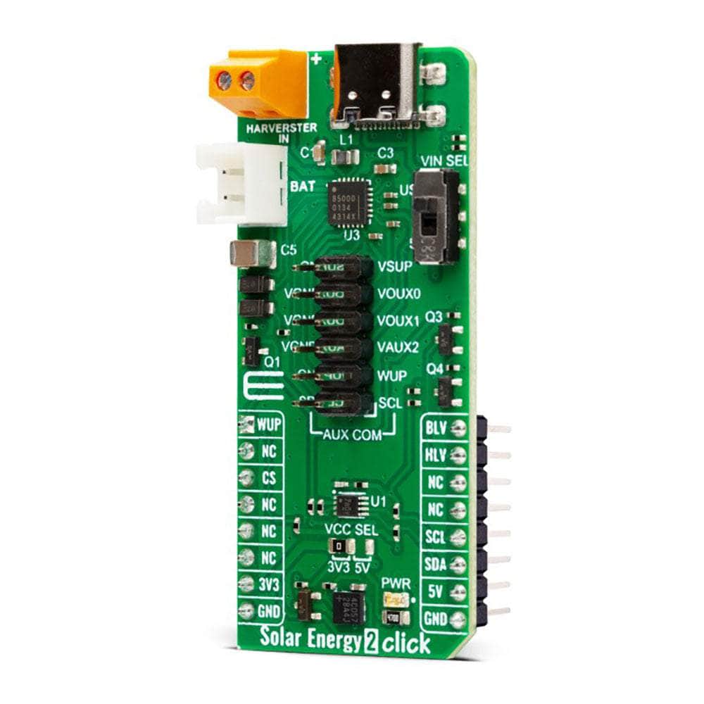
Das Solar Energy 2 Click Board™: Nutzen Sie die Kraft der Sonne
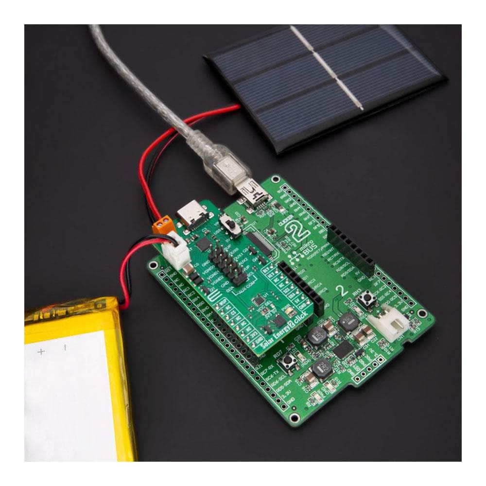
Wir stellen das Solar Energy 2 Click Board™ vor, die kompakte Zusatzplatine, die das Aufladen von Batterien durch Solarenergie und mehr revolutioniert. Mit seinen erweiterten Funktionen und seiner Spitzentechnologie ist diese Platine ein Wendepunkt in der Welt der Energiegewinnung.
Effiziente Energiegewinnung
Das Solar Energy 2 Click Board™ verfügt über den EM8500, einen leistungsstarken Management-Controller mit einer Energiegewinnungsschnittstelle von EM Microelectronic. Dieser Controller wurde speziell dafür entwickelt, die Effizienz bei der Energiegewinnung aus verschiedenen Gleichstromquellen, einschließlich Photovoltaik (Solar) und thermoelektrischen Generatoren (TEG), zu maximieren. Verabschieden Sie sich von herkömmlichen Lademethoden und begrüßen Sie die Zukunft erneuerbarer Energien.
Starke Leistung
Mit dem Solar Energy 2 Click Board™ können Sie Ihren LiPo-Akku oder Superkondensator und sogar herkömmliche Kondensatoren mühelos aufladen. Der EM8500-Controller sorgt für zuverlässiges und schnelles Aufladen und ist damit eine ideale Lösung für eine Vielzahl von Anwendungen.
Vielseitige Einsatzmöglichkeiten
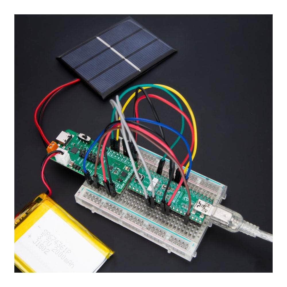
Nutzen Sie das Potenzial des Solar Energy 2 Click Board™ für verschiedene stromabhängige Geräte. Es ist die perfekte Wahl für drahtlose Sensornetzwerke, Umweltüberwachungsgeräte, tragbare und tragbare Gesundheitsüberwachungsgeräte, batteriebetriebene Plattformen und andere stromsparende, autarke Geräte. Erleben Sie unterbrechungsfreie Stromversorgung und Freiheit wie nie zuvor.
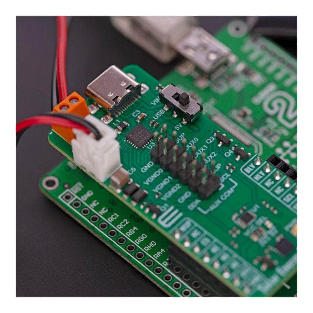
Nahtlose Integration
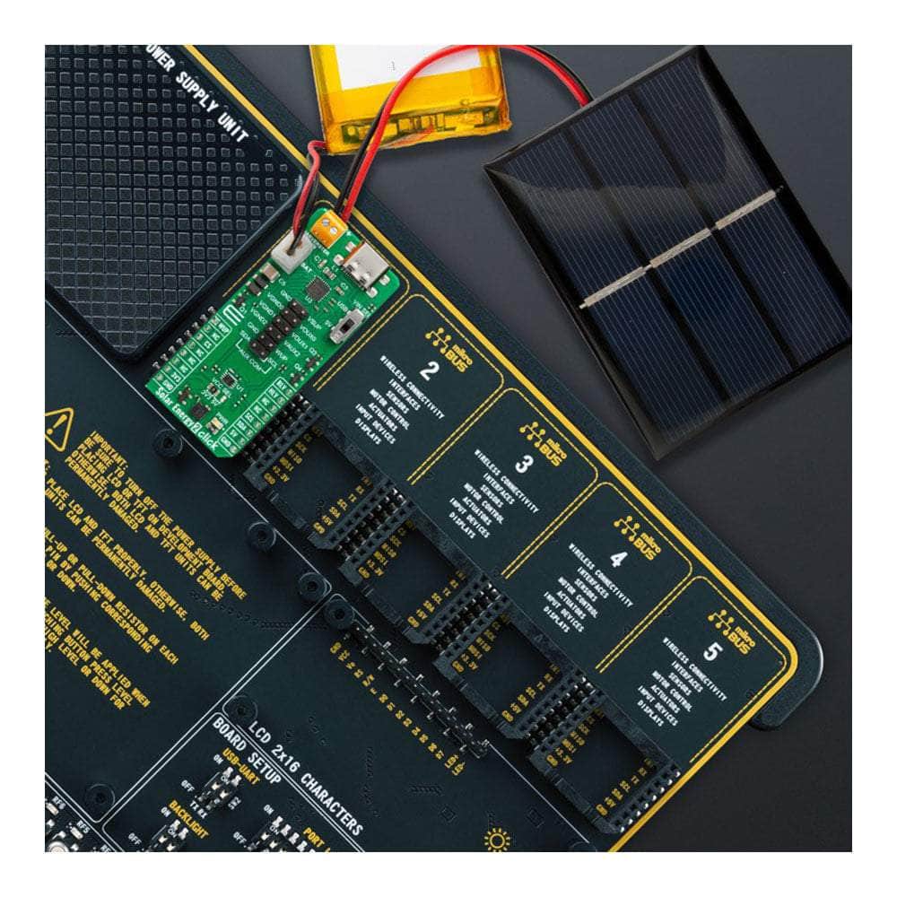
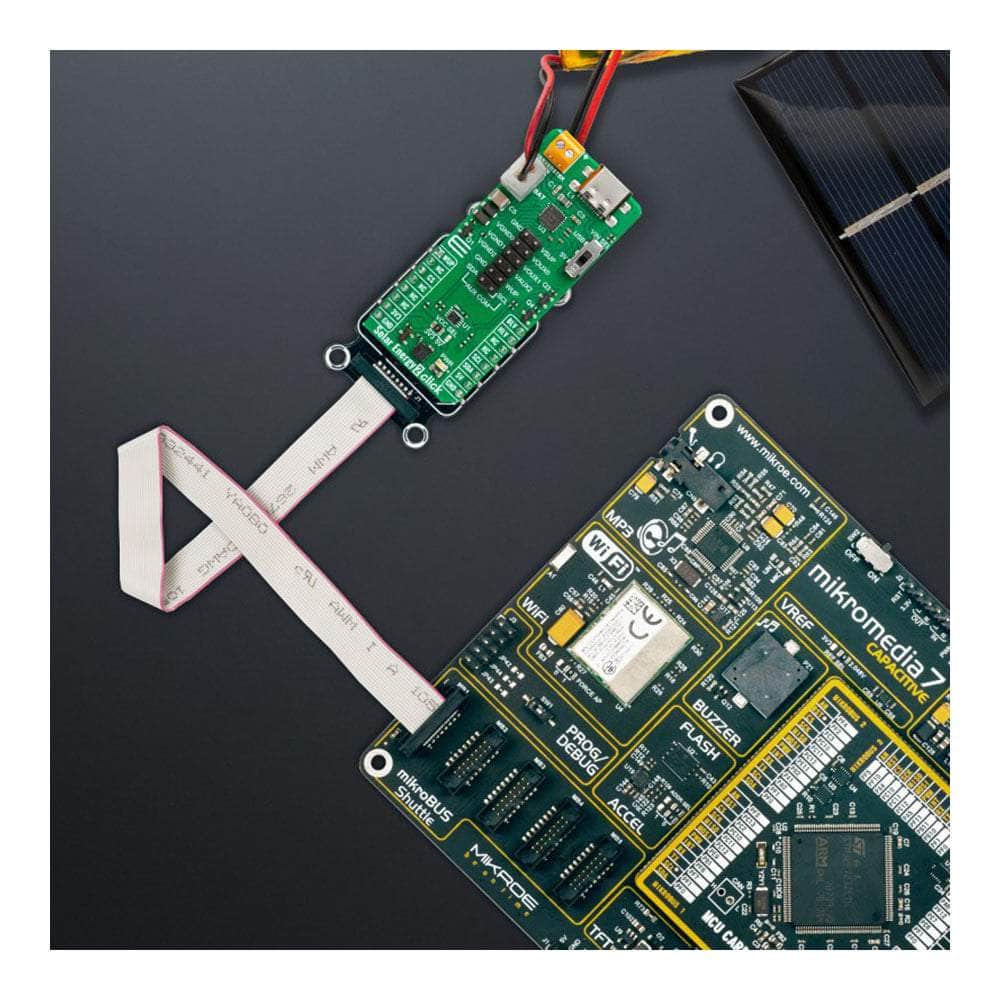
Das Solar Energy 2 Click Board™ lässt sich dank seiner Kompatibilität mit der mikroBUS™-Buchse nahtlos in Ihr vorhandenes System integrieren. Es wird mit einer mikroSDK-kompatiblen Bibliothek geliefert, die eine vereinfachte Softwareentwicklung ermöglicht und es Ihnen ermöglicht, sein volles Potenzial mühelos auszuschöpfen.
Einsatzbereit
Verschwenden Sie keine Zeit mit ungetesteten Produkten. Das Solar Energy 2 Click Board™ wird vollständig getestet und ist sofort einsatzbereit. Nutzen Sie die Kraft der Sonne und bringen Sie Ihre Projekte mit dieser innovativen Lösung auf ein neues Niveau.
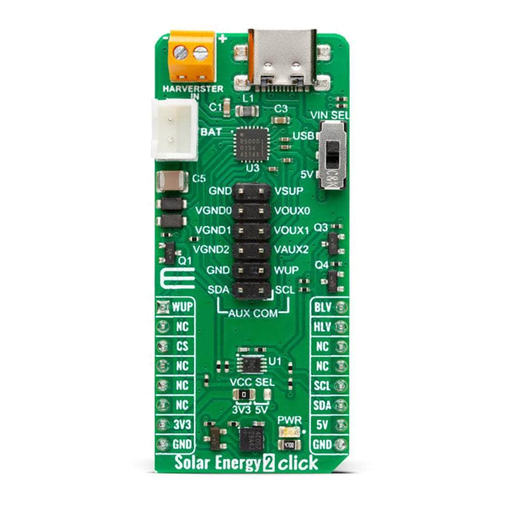
How Does The Solar Energy 2 Click Board™ Work?
The Solar Energy 2 Click Board™ is based on the EM8500, a power management controller with an energy harvesting interface from EM Microelectronic. The EM8500 is flexible in operation and can use different energy banks such as primary cell batteries, gold capacitors, and supercapacitors. It can work in harvesting sources in μW to mW range thanks to an ultra-low power DC-DC boost converter with very high efficiency. The EN8500 uses short-term storage (STS) element (100μF capacitor) to speed up system start-up. Besides fast start-up time over battery power, the LTS element (long-term storage) controls the minimum and maximum voltages, thus preventing damage to the battery. The onboard PMU with a built-in mechanism will extend the battery life if using a non-rechargeable battery.
The Solar Energy 2 Click Board™ can supply the external application through the VSUP and VAUX0-2 pins and correspondent GNDs of the 12-pin AUX COM header. On the VSUP pin, which is the main supply output, the wake-up function allows the automatic enabling of the supply after a given time. The AUX (auxiliary) output pins can output regulated voltages from 1.2 to 2.6V. Onboard EEPROM stores device configuration data, such as minimum and maximum voltage monitors, which will stop the DC-DC convertor, thus limiting the power loss. On EEPROM can be stored data for the VAUX0-2 and VGND0-2 pins, which besides the voltage output, can be used to store data for disconnecting any of these pins.
There are three modes in which Solar Energy 2 Click can operate. In Normal mode, the battery is connected and is in operating range. The LTS Protection mode is activated when the LTS voltage drops below minimum battery operation. In this mode is activated under-voltage protection. Finally, there is a Sleep mode where the VSUP is not supplied, and the communication with the host MCU is off. Sleep mode exit can be activated over the wake-up pin or by an internal timer.
The EN8500 also comes with several features, such as under-voltage, over-voltage, min/max voltage warning, USB connected status, lux-meter, and more. The lux-meter can run in three modes: Fully Automatic mode, Automatic Range Selection, and Fully Manual mode. The lux-meter determines current ranges by the harvesting element in 1 μA steps. On Solar Energy 2 Click, a VIN SEL switch allows the EN8500 to use the 5V rail from the mikroBUS™ socket or the 5V from the onboard USB Type-C connector as its supply. The EM8500 can detect the power on this line but can't determine if it is from the USB C or the 5V rail of the mikroBUS™ socket.
Although the EN8500 uses 5V rail only for its power management, the Solar Energy 2 Click can work with 3.3V systems, too. This Click board™ features the PCA9306, a dual bidirectional voltage level translator from Texas Instruments. As a low-voltage-side reference voltage, this translator uses the VSUP from the EN8500, while the high-side is the one selected via the VCC SEL jumper. In the same manner, several MOSFETs are used for other onboard interconnections.
The Solar Energy 2 Click Board™ uses a standard 2-Wire I2C interface to communicate with the host MCU and supports Standard, Fast, and High-Speed communication. As mentioned, the EN8500 can exit sleep mode via the wake-up functions, which can be the WUP pin of the mikroBUS™ socket or the WUP pin of the AUX COM header. The EN8500 uses two more pins to send statuses to the host MCU. The HLV is used as a harvester-energy levels detection status, while the BLV is used for battery voltage levels monitoring.
The Solar Energy 2 Click Board™ can operate with either 3.3V or 5V logic voltage levels selected via the VCC SEL jumper. This way, both 3.3V and 5V capable MCUs can use the communication lines properly. However, the Click board™ comes equipped with a library containing easy-to-use functions and an example code that can be used, as a reference, for further development.
SPECIFICATIONS
| Type | Battery charger, Solar Charger |
| Applications | It can be used for powering wireless sensor networks, environmental monitoring devices, portable and wearable health monitoring devices, battery operating platforms, and similar low-power self-sustained devices |
| On-board modules | EM8500 - power management controller with an energy harvesting interface from EM Microelectronic |
| Key Features | Variety of DC harvesting sources including thermal electric generators (TEG) or photovoltaic (solar), sources in the μW to mW range, flexible operation with primary cell battery, gold capacitors, and supercapacitors, auxiliary voltage output, programmable thresholds, onboard EEPROM, and more |
| Interface | I2C |
| Compatibility | mikroBUS |
| Click board size | L (57.15 x 25.4 mm) |
| Input Voltage | 3.3V or 5V |
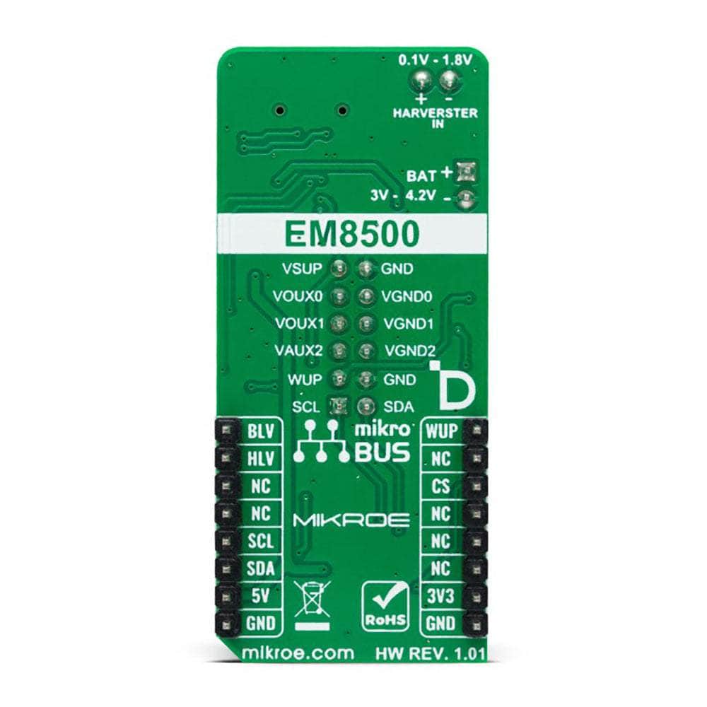
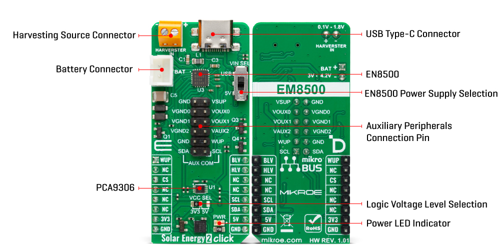
PINOUT DIAGRAM
This table shows how the pinout of the Solar Energy 2 Click Board™ corresponds to the pinout on the mikroBUS™ socket (the latter shown in the two middle columns).
| Notes | Pin | Pin | Notes | ||||
|---|---|---|---|---|---|---|---|
| Wake Up | WUP | 1 | AN | PWM | 16 | BLV | Battery Voltage Level Indicator |
| NC | 2 | RST | INT | 15 | HLV | Harvester Voltage Level Indicator | |
| NC | 3 | CS | RX | 14 | NC | ||
| NC | 4 | SCK | TX | 13 | NC | ||
| NC | 5 | MISO | SCL | 12 | SCL | I2C Clock | |
| NC | 6 | MOSI | SDA | 11 | SDA | I2C Data | |
| Power Supply | 3.3V | 7 | 3.3V | 5V | 10 | 5V | Power Supply |
| Ground | GND | 8 | GND | GND | 9 | GND | Ground |
ONBOARD SETTINGS AND INDICATORS
| Label | Name | Default | Description |
|---|---|---|---|
| LD1 | PWR | - | Power LED Indicator |
| JP2 | VCC SEL | Left | Logic Level Voltage Selection 3V3/5V: Left position 3V3, Right position 5V |
| SW1 | VIN SEL | Upper | Power Supply Selection USB/5V: Upper position USB, Lower position 5V |
SOLAR ENERGY 2 CLICK ELECTRICAL SPECIFICATIONS
| Description | Min | Typ | Max | Unit |
|---|---|---|---|---|
| Supply Voltage | 3.3 | - | 5 | V |
| AUX Output Voltage | 1.2 | - | 2.6 | V |
| DC Harvesting Source Voltage | 0.1 | 0.5 | 1.8 | V |
Software Support
Software Support
We provide a library for the Solar Energy 2 Click Board™ as well as a demo application (example), developed using MIKROE compilers. The demo can run on all the main MIKROE development boards.
The package can be downloaded/installed directly from NECTO Studio The package Manager (recommended), downloaded from our LibStock™ or found on MikroE Github account.
Library Description
This library contains API for the Solar Energy 2 Click Board™ driver.
Key functions
-
solarenergy2_set_pwr_current_sourceSolar Energy 2 power source selection function. -
solarenergy2_config_abs_voltageSolar Energy 2 config absolute voltage function. -
solarenergy2_set_mppt_ratioSolar Energy 2 set MPPT ratio function.
Example Description
This library contains API for the Solar Energy 2 Click Board™ driver. This driver provides functions to configure the power management controller with an energy harvesting interface.
void application_task ( void )
 {
     if ( SOLARENERGY2_OK == solarenergy2_get_status( &solarenergy2, &status ) )
     {
         if  ( SOLARENERGY2_OK == solarenergy2_get_bat_vtg_status( &solarenergy2, &vld_status ) )
         {
             display_status( );
         }
     }
     Delay_ms( 5000 );
 }
The full application code, and ready to use projects can be installed directly from NECTO Studio The package Manager (recommended), downloaded from our LibStock™ or found on MikroE Github account.
Other MikroE Libraries used in the example:
- MikroSDK.Board
- MikroSDK.Log
- Click.SolarEnergy2
Additional Notes and Information
Depending on the development board you are using, you may need USB UART Click Board™, USB UART 2 Click or RS232 Click to connect to your PC, for development systems with no UART to USB interface available on the board. UART terminal is available in all MIKROE compilers.
MIKROSDK
The Solar Energy 2 Click Board™ is supported with mikroSDK - MIKROE Software Development Kit. To ensure proper operation of mikroSDK compliant Click board™ demo applications, mikroSDK should be downloaded from the LibStock and installed for the compiler you are using.
Solarenergie 2 Click Board
Frequently Asked Questions
Have a Question?
Be the first to ask a question about this.