Key Features
Overview
Introducing the DC Motor 25 Click Board™ - The Ultimate Brushed DC Motor Driver!
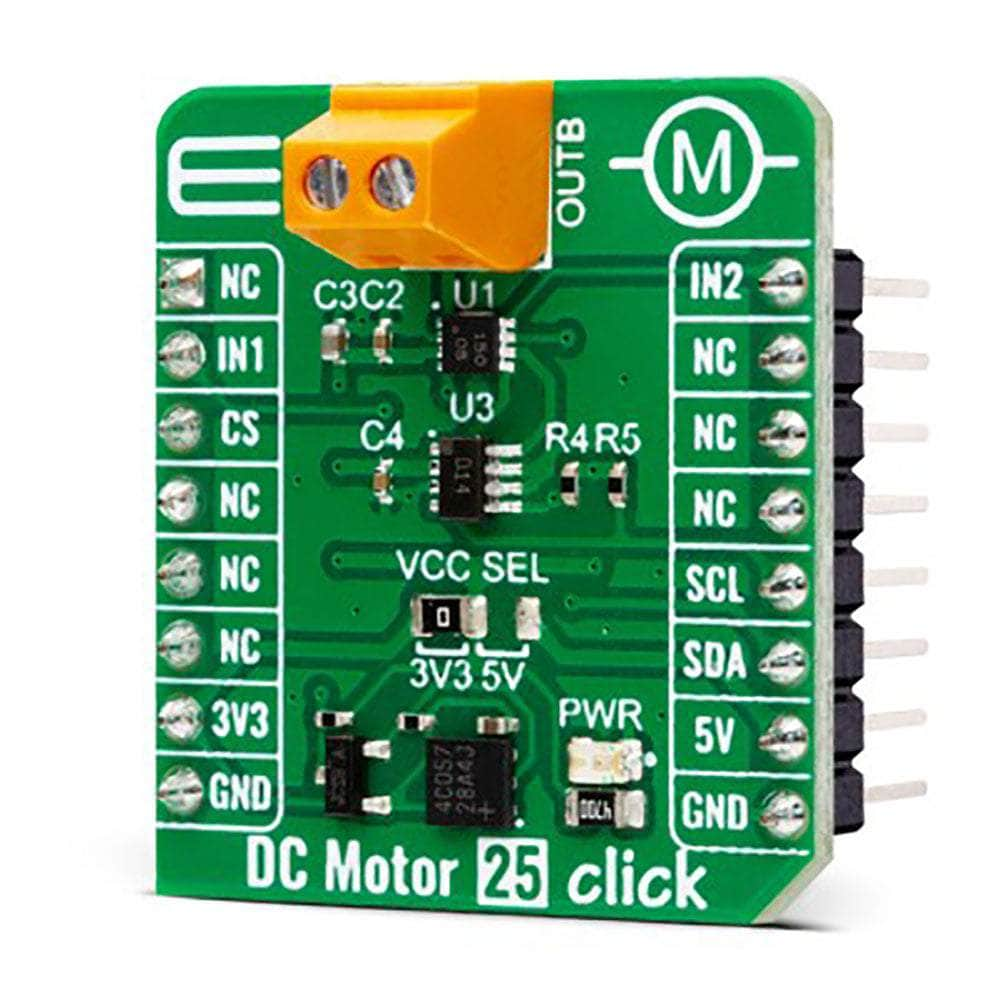
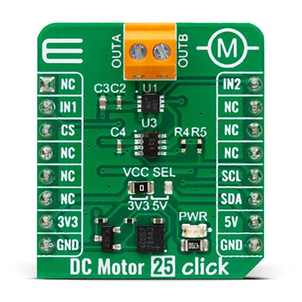
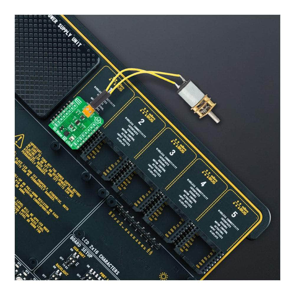
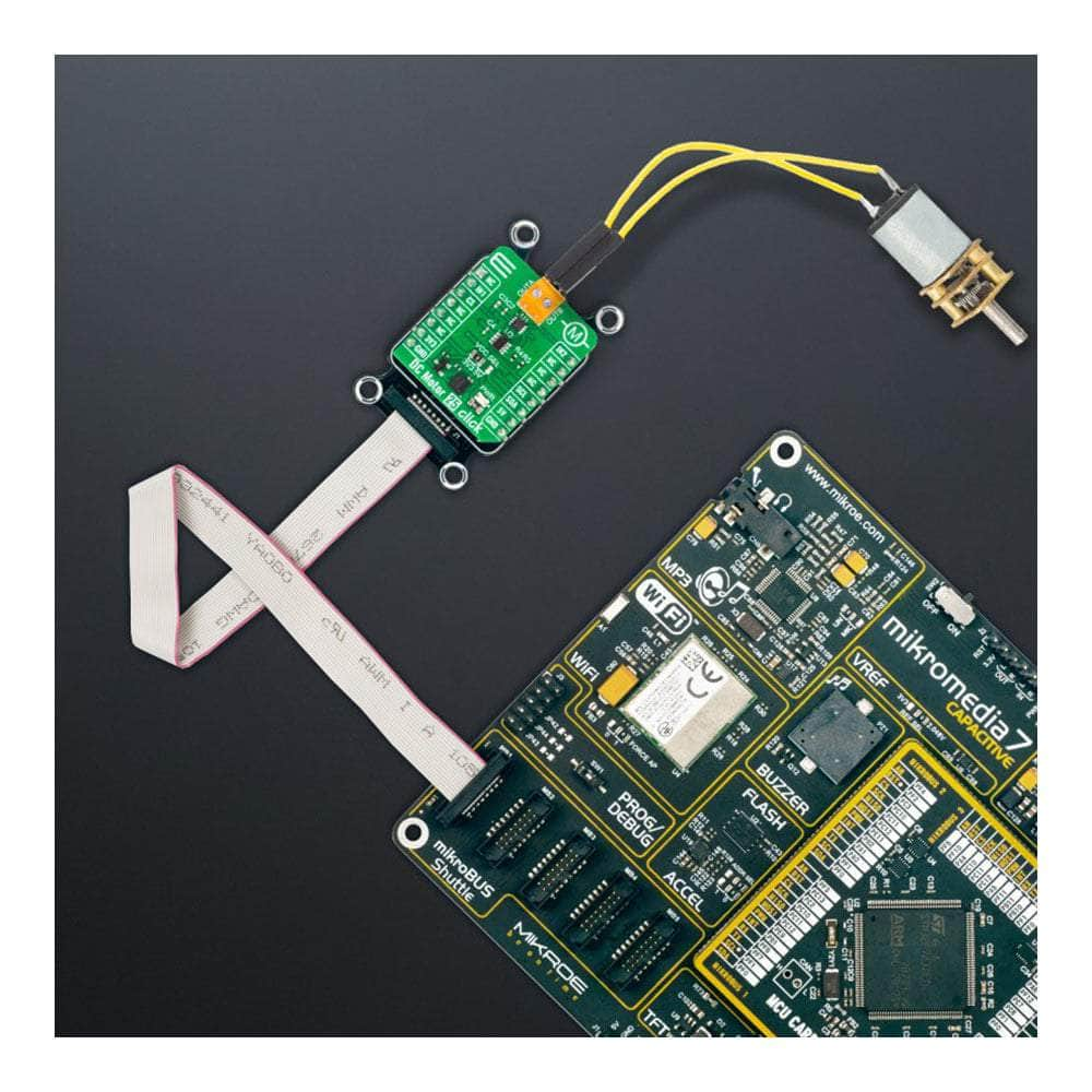
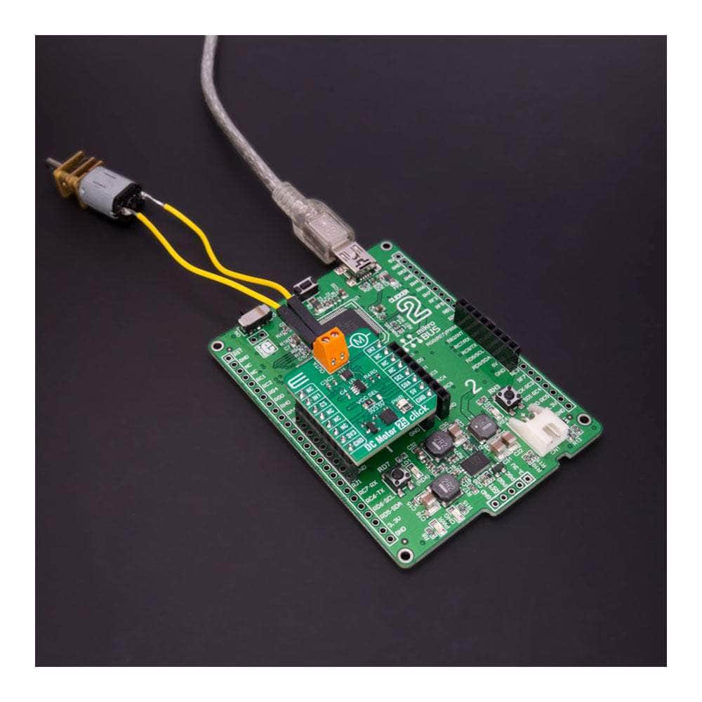
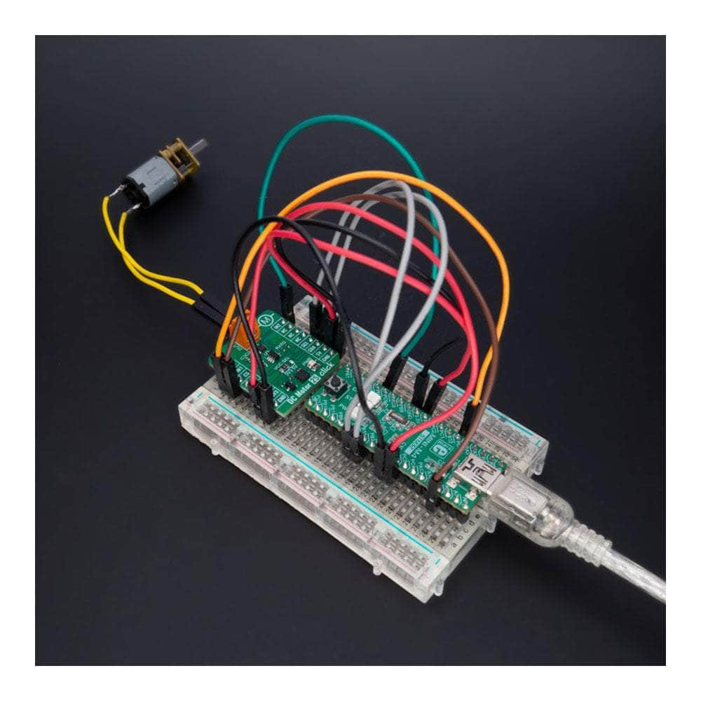
Unlock the full potential of your brushed DC motors with the all-new DC Motor 25 Click Board™! This compact add-on board is designed to deliver outstanding performance and versatility, thanks to the cutting-edge A3908 low-voltage bidirectional DC motor driver from Allegro Microsystems.
Experience Unparalleled Power and Efficiency
With an operating voltage range fully compatible with mikroBUS™ power rails and able to handle output currents of up to 500mA, the DC Motor 25 Click Board™ is perfect for a wide range of applications. Its unique output full-bridge incorporates source-side linear operation, ensuring a constant voltage across the motor coil for maximum efficiency.
Enjoy Ultimate Control and Flexibility
Logic input pins are at your disposal for precise control over the motor's direction of rotation, brake, and standby modes. This means you can easily fine-tune your device's performance to fit your specific needs, whether it's robotic actuators, pumps, battery-powered toys and games, low-noise instrumentation systems, or any other application that requires a reliable DC motor driver.
Stay Protected with Complete Protection Capabilities
The DC Motor 25 Click Board™ comes equipped with comprehensive protection features, ensuring robust and reliable operation in even the most demanding environments. Keep your devices running smoothly and safely, no matter the challenge.
Effortless Software Development with mikroSDK
Thanks to its mikroSDK-compliant library, the DC Motor 25 Click Board™ streamlines software development by providing you with various helpful functions. This means you can spend less time coding and more time enjoying your newly enhanced devices!
Plug and Play for a Seamless Experience
Designed for immediate use on a system equipped with a mikroBUS™ socket, the DC Motor 25 Click Board™ comes as a fully tested product. Get ready to experience the future of brushed DC motor drivers today!
Downloads
Wir stellen das DC Motor 25 Click Board™ vor – den ultimativen Treiber für bürstenbehaftete Gleichstrommotoren!
Schöpfen Sie das volle Potenzial Ihrer bürstenbehafteten Gleichstrommotoren mit dem brandneuen DC Motor 25 Click Board™! Diese kompakte Zusatzplatine ist auf herausragende Leistung und Vielseitigkeit ausgelegt, dank des hochmodernen bidirektionalen Niederspannungs-Gleichstrommotortreibers A3908 von Allegro Microsystems.
Erleben Sie beispiellose Leistung und Effizienz
Mit einem Betriebsspannungsbereich, der vollständig mit mikroBUS™-Stromschienen kompatibel ist und Ausgangsströme von bis zu 500 mA verarbeiten kann, ist das DC Motor 25 Click Board™ perfekt für eine Vielzahl von Anwendungen geeignet. Seine einzigartige Ausgangsvollbrücke umfasst einen linearen Betrieb auf der Quellseite und gewährleistet eine konstante Spannung über der Motorspule für maximale Effizienz.
Genießen Sie ultimative Kontrolle und Flexibilität
Für die präzise Steuerung der Drehrichtung, der Brems- und Standby-Modi des Motors stehen Ihnen Logik-Eingangspins zur Verfügung. Das bedeutet, dass Sie die Leistung Ihres Geräts ganz einfach an Ihre spezifischen Anforderungen anpassen können, egal ob es sich um Roboterantriebe, Pumpen, batteriebetriebene Spielzeuge und Spiele, geräuscharme Instrumentierungssysteme oder jede andere Anwendung handelt, die einen zuverlässigen Gleichstrommotortreiber erfordert.
Bleiben Sie geschützt mit umfassenden Schutzfunktionen
Das DC Motor 25 Click Board™ ist mit umfassenden Schutzfunktionen ausgestattet, die einen robusten und zuverlässigen Betrieb selbst in den anspruchsvollsten Umgebungen gewährleisten. Sorgen Sie dafür, dass Ihre Geräte reibungslos und sicher laufen, egal, vor welcher Herausforderung sie stehen.
Mühelose Softwareentwicklung mit mikroSDK
Dank seiner mikroSDK-kompatiblen Bibliothek vereinfacht das DC Motor 25 Click Board™ die Softwareentwicklung, indem es Ihnen verschiedene hilfreiche Funktionen bietet. Das bedeutet, dass Sie weniger Zeit mit dem Codieren verbringen und mehr Zeit damit verbringen können, Ihre neu verbesserten Geräte zu genießen!
Plug and Play für ein nahtloses Erlebnis
Das DC Motor 25 Click Board™ ist für den sofortigen Einsatz in einem System mit einer mikroBUS™-Buchse konzipiert und wird als vollständig getestetes Produkt geliefert. Machen Sie sich bereit, die Zukunft der bürstenbehafteten DC-Motortreiber noch heute zu erleben!
| General Information | |
|---|---|
Part Number (SKU) |
MIKROE-5523
|
Manufacturer |
|
| Physical and Mechanical | |
Weight |
0.02 kg
|
| Other | |
Country of Origin |
|
HS Code Customs Tariff code
|
|
EAN |
8606027384974
|
Warranty |
|
Frequently Asked Questions
Have a Question?
-
Is the DC Motor 25 Click Board™ a tested product?
Yes, the DC Motor 25 Click Board™ comes as a fully tested product, ready for use on a system equipped with the mikroBUS™ socket.
-
What is the mikroBUS™ socket?
The mikroBUS™ socket is a standardized interface that allows you to connect various Click boards™ to a development system. The DC Motor 25 Click Board™ is designed to be used with a system equipped with a mikroBUS™ socket.
-
How can I develop software for the DC Motor 25 Click Board™?
The DC Motor 25 Click Board™ is supported by a mikroSDK-compliant library, which includes functions that simplify software development. You can use these functions to create your software for controlling DC motors easily.
-
What kind of protection capabilities does the DC Motor 25 Click Board™ offer?
The board has complete protection capabilities, including overcurrent protection and thermal protection, ensuring robust and reliable operation.
-
How is the motor direction of rotation controlled?
The DC Motor 25 Click Board™ provides logic input pins to control the motor direction of rotation, brake, and standby modes.
-
What is the maximum output current of the A3908 motor driver?
The A3908 motor driver on the DC Motor 25 Click Board™ can provide output currents up to 500mA.
-
What is the operating voltage range of the A3908 motor driver?
The A3908 motor driver on the DC Motor 25 Click Board™ is rated for an operating voltage range compatible with the mikroBUS™ power rails.
-
What is the DC Motor 25 Click Board™?
The DC Motor 25 Click Board™ is a compact add-on board featuring the A3908 brushed DC motor driver from Allegro Microsystems. It is designed to control brushed DC motors in various applications such as robotic actuators, pumps, battery-powered toys, low-noise instrumentation systems, and more.


