


Mikroelektronika d.o.o.
Buck 22 Click Board™
Buck 22 Click Board™
SKU: MIKROE-5446
Verfügbarkeit für Abholungen konnte nicht geladen werden


Key Features
Overview
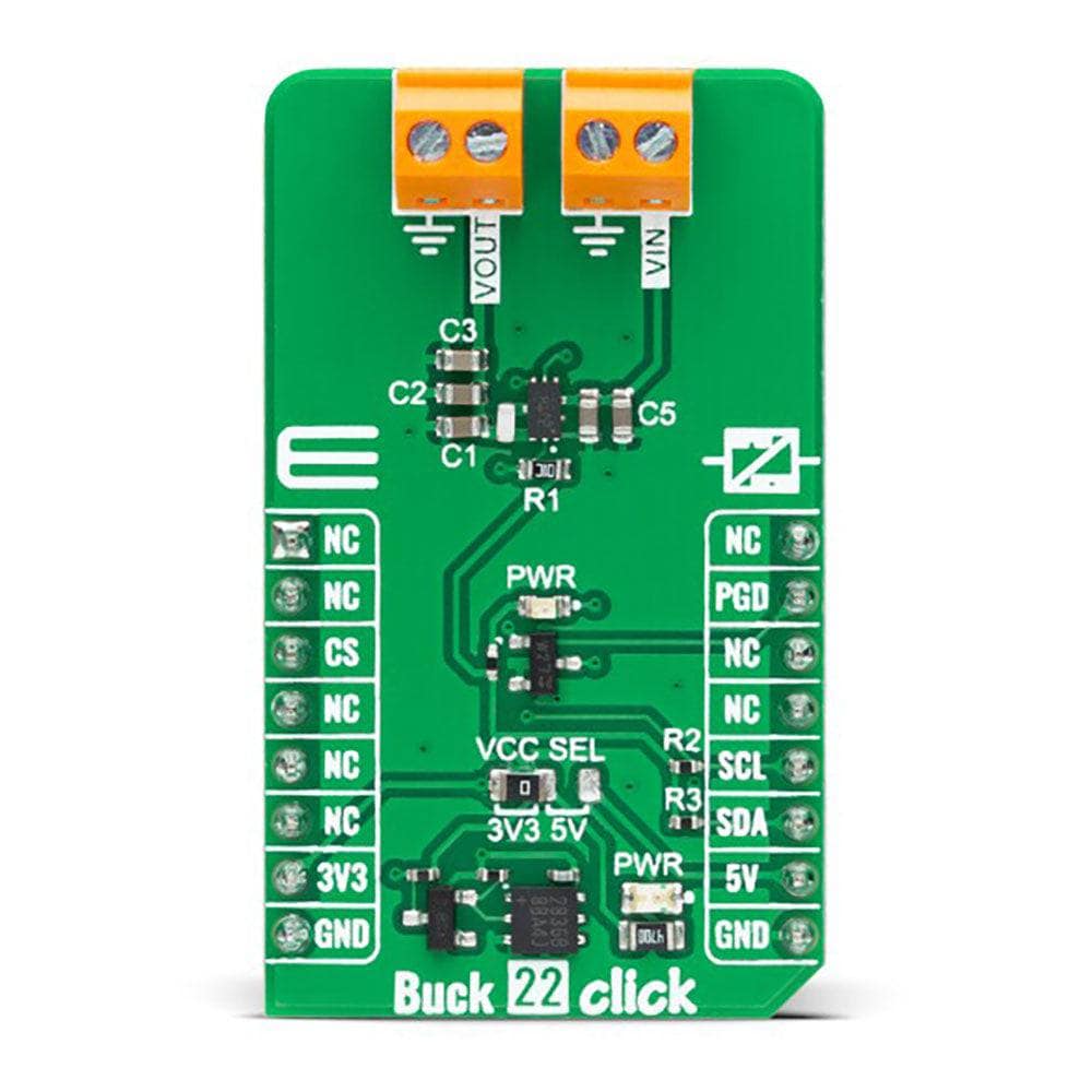
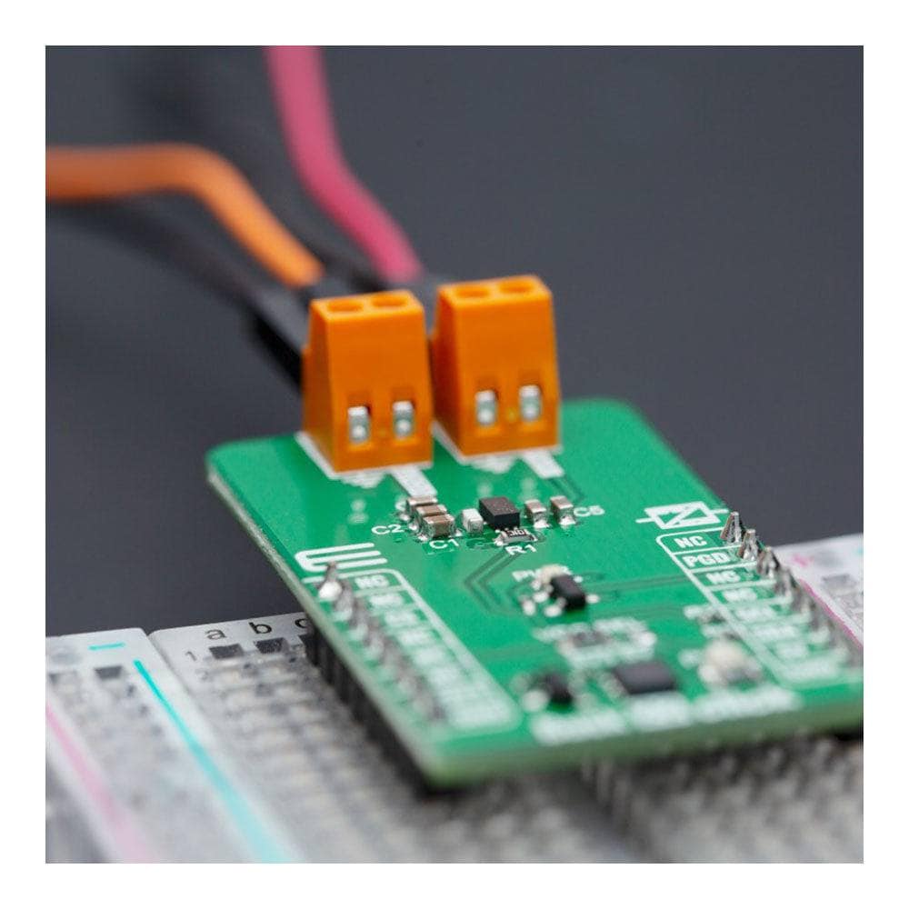
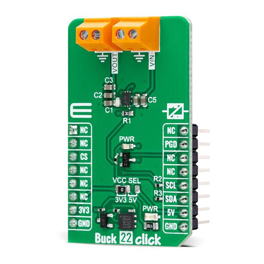
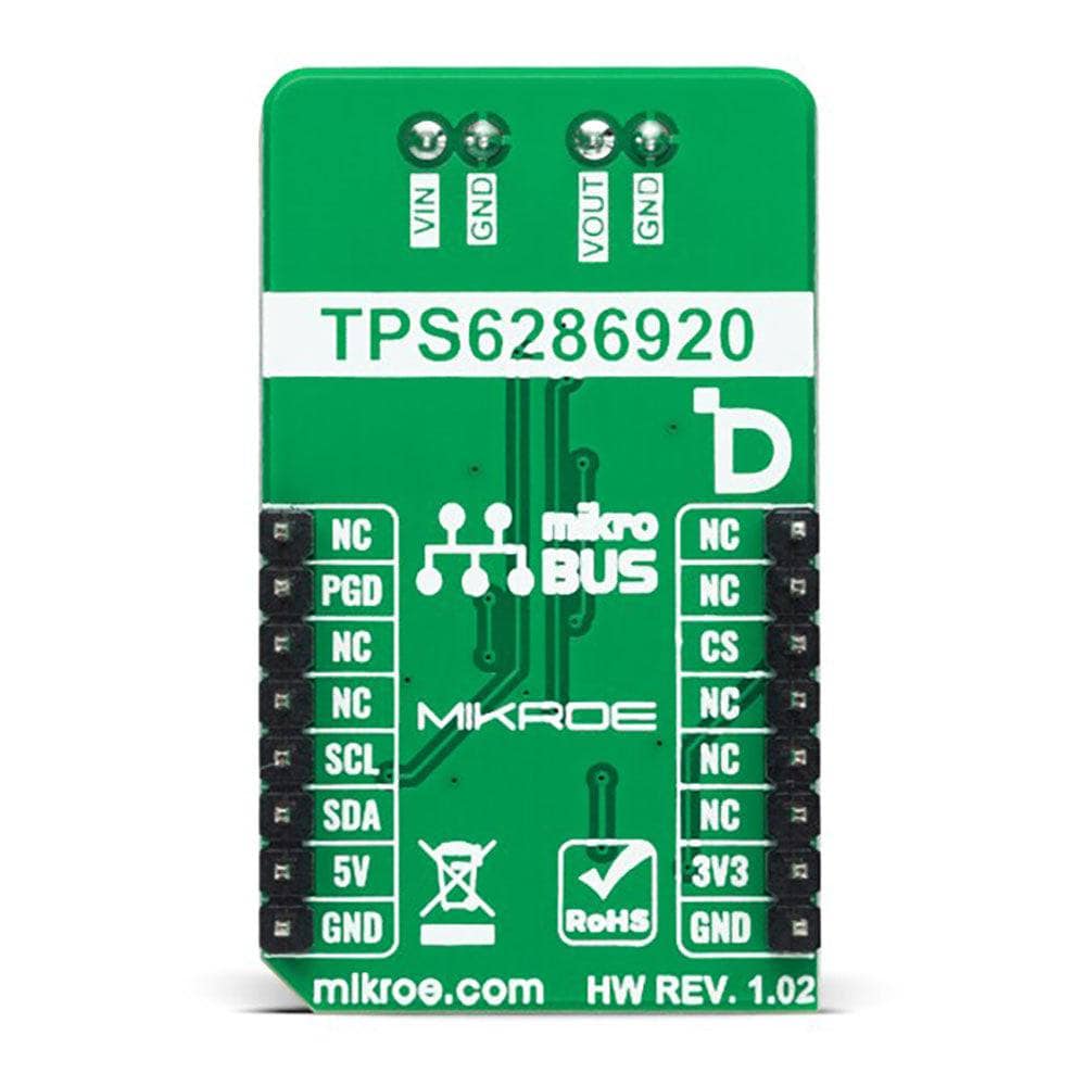
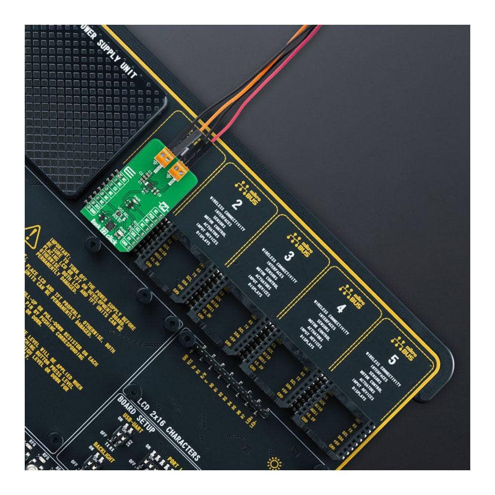
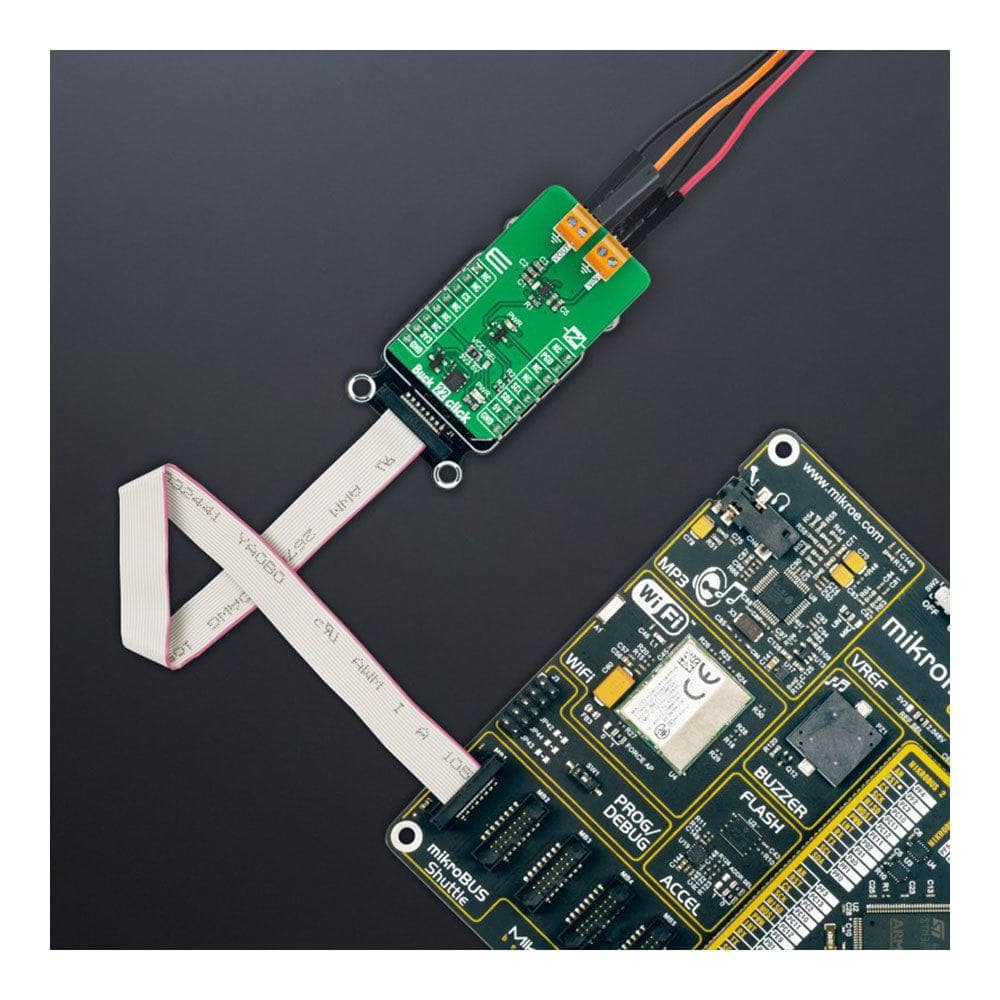
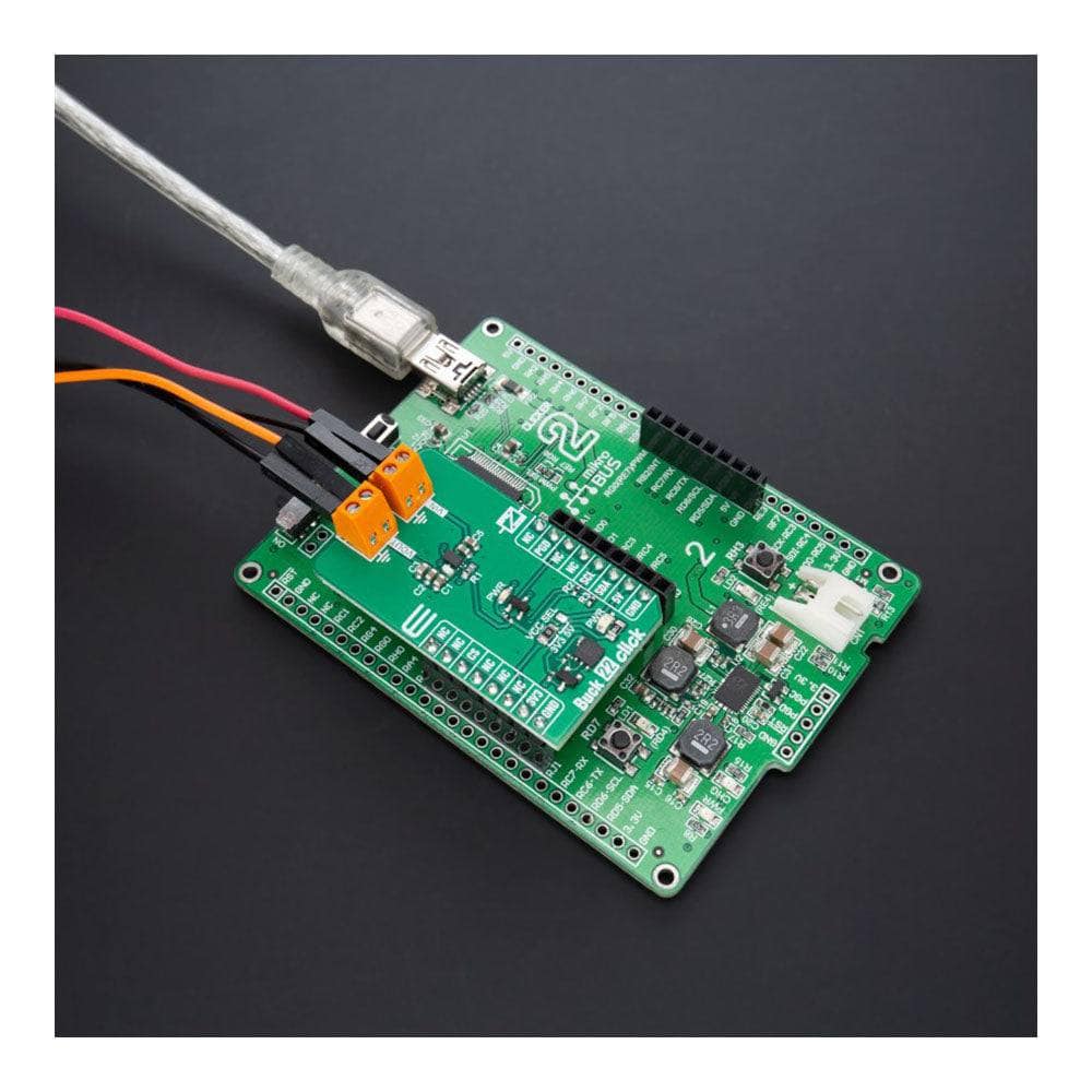
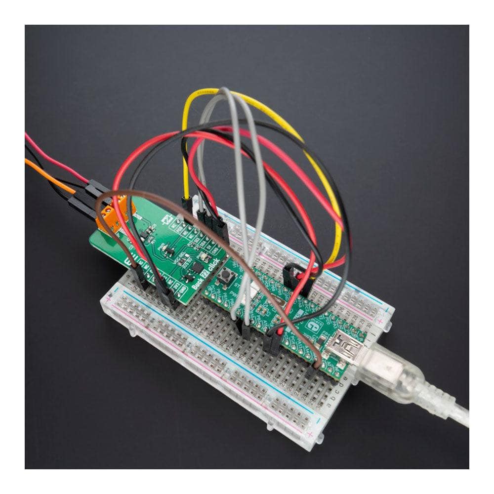
The Buck 22 Click Board™ is a compact add-on board that steps down the voltage from its input (supply) to its output (load). This board features the TPS62869, a high-frequency synchronous step-down converter with an I2C interface from Texas Instruments, providing an efficient, adaptive, and high power-density solution. The TPS62869 operates in PWM mode at medium to heavy loads (for the slightest output voltage ripple). It automatically enters Power-Save Mode operation at a light load to maintain high efficiency over the entire output load current range. With its DCS-Control™ architecture, excellent load transient performance and tight output voltage accuracy are achieved alongside adjustable output voltage range from 0.8V to 3.35V with a 10mV step size. This Click board™ is used to derive the required input voltage from a higher voltage source for FPGAs, ASICs, video chipsets, solid-state drives, and many more.
The Buck 22 Click Board™ is supported by a mikroSDK-compliant library, which includes functions that simplify software development. This Click board™ comes as a thoroughly tested product, ready to be used on a system equipped with the mikroBUS™ socket.
Downloads
Das Buck 22 Click Board™ ist eine kompakte Zusatzplatine, die die Spannung von ihrem Eingang (Versorgung) zu ihrem Ausgang (Last) heruntersetzt. Diese Platine verfügt über den TPS62869, einen hochfrequenten synchronen Abwärtswandler mit einer I2C-Schnittstelle von Texas Instruments, der eine effiziente, adaptive und hochleistungsdichte Lösung bietet. Der TPS62869 arbeitet bei mittleren bis hohen Lasten im PWM-Modus (für die geringste Welligkeit der Ausgangsspannung). Bei geringer Last wechselt er automatisch in den Energiesparmodus, um eine hohe Effizienz über den gesamten Ausgangslaststrombereich aufrechtzuerhalten. Mit seiner DCS-Control™-Architektur werden eine ausgezeichnete Lastübergangsleistung und eine hohe Ausgangsspannungsgenauigkeit sowie ein einstellbarer Ausgangsspannungsbereich von 0,8 V bis 3,35 V mit einer Schrittweite von 10 mV erreicht. Dieses Click Board™ wird verwendet, um die erforderliche Eingangsspannung von einer höheren Spannungsquelle für FPGAs, ASICs, Videochipsätze, Halbleiterlaufwerke und vieles mehr abzuleiten.
Das Buck 22 Click Board™ wird von einer mikroSDK-kompatiblen Bibliothek unterstützt, die Funktionen enthält, die die Softwareentwicklung vereinfachen. Dieses Click Board™ ist ein gründlich getestetes Produkt und kann auf einem System verwendet werden, das mit der mikroBUS™-Buchse ausgestattet ist.
| General Information | |
|---|---|
Part Number (SKU) |
MIKROE-5446
|
Manufacturer |
|
| Physical and Mechanical | |
Weight |
0.02 kg
|
| Other | |
EAN |
8606027386398
|
Frequently Asked Questions
Have a Question?
Be the first to ask a question about this.