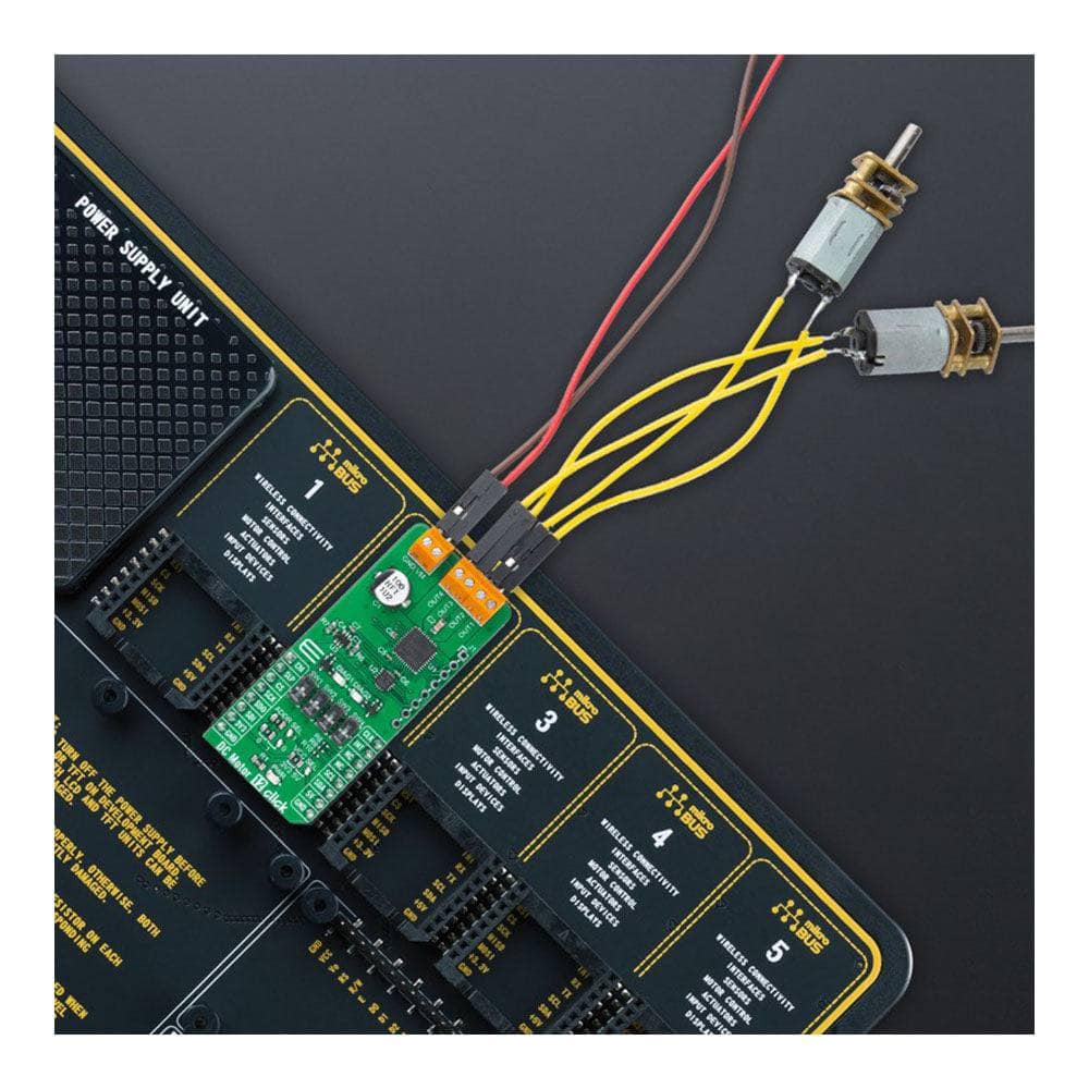
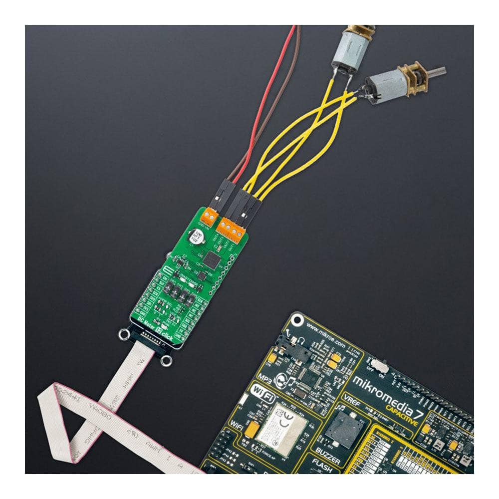
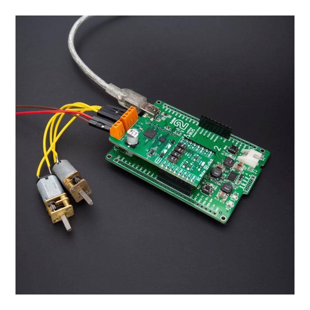
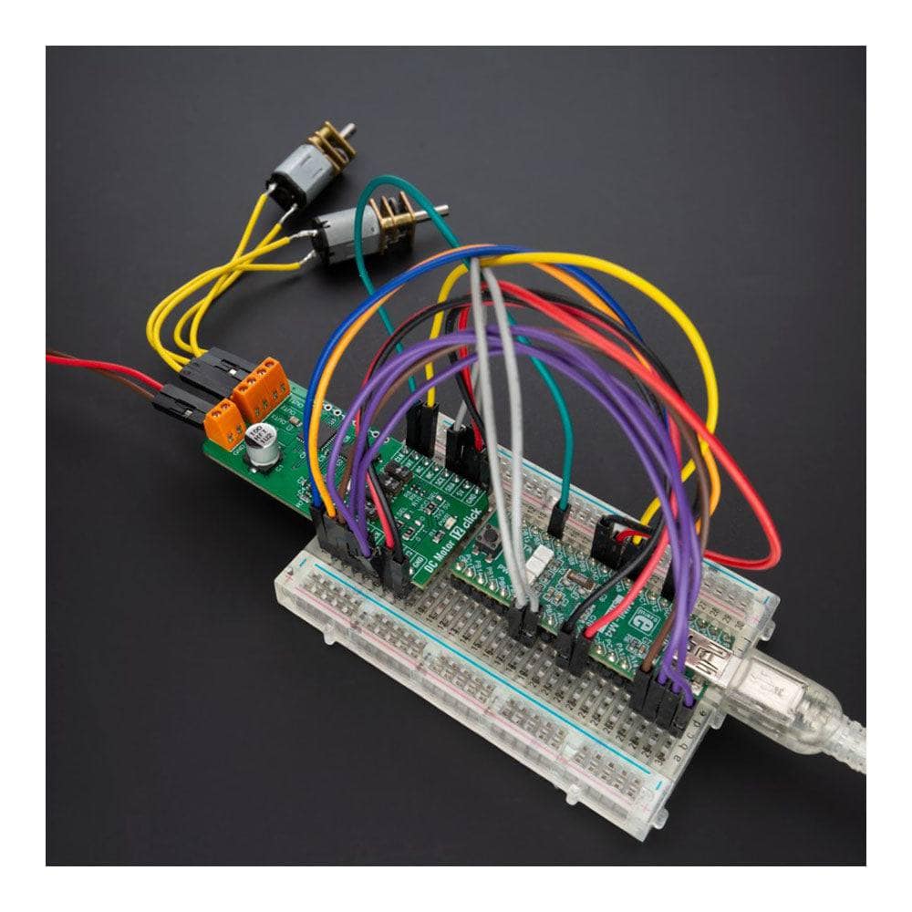
Gleichstrommotor 12 Click-Platine
Key Features
- Treiber für einen oder zwei Gleichstrommotoren, direkte PWM-Steuerung oder über SPI-Schnittstelle, wählbare Motorsteuerungsfunktionen und Betriebsmodi, Ruhemodus und Stromüberwachung, umfassender Schutz und Diagnose und mehr
- Basierend auf dem TB9054FTG - Bürsten-Gleichstrommotortreiber von Toshiba Semiconductor
- Kann für Automobilanwendungen (AEC-Q100 Grade 1-zertifiziert) verwendet werden, beispielsweise zur Steuerung der Drosselklappe, der Motorventile, der einklappbaren Außenspiegel und der Sitzheizung.
- mikroBUS: I2C-, SPI- und PWM-Schnittstellen
Overview
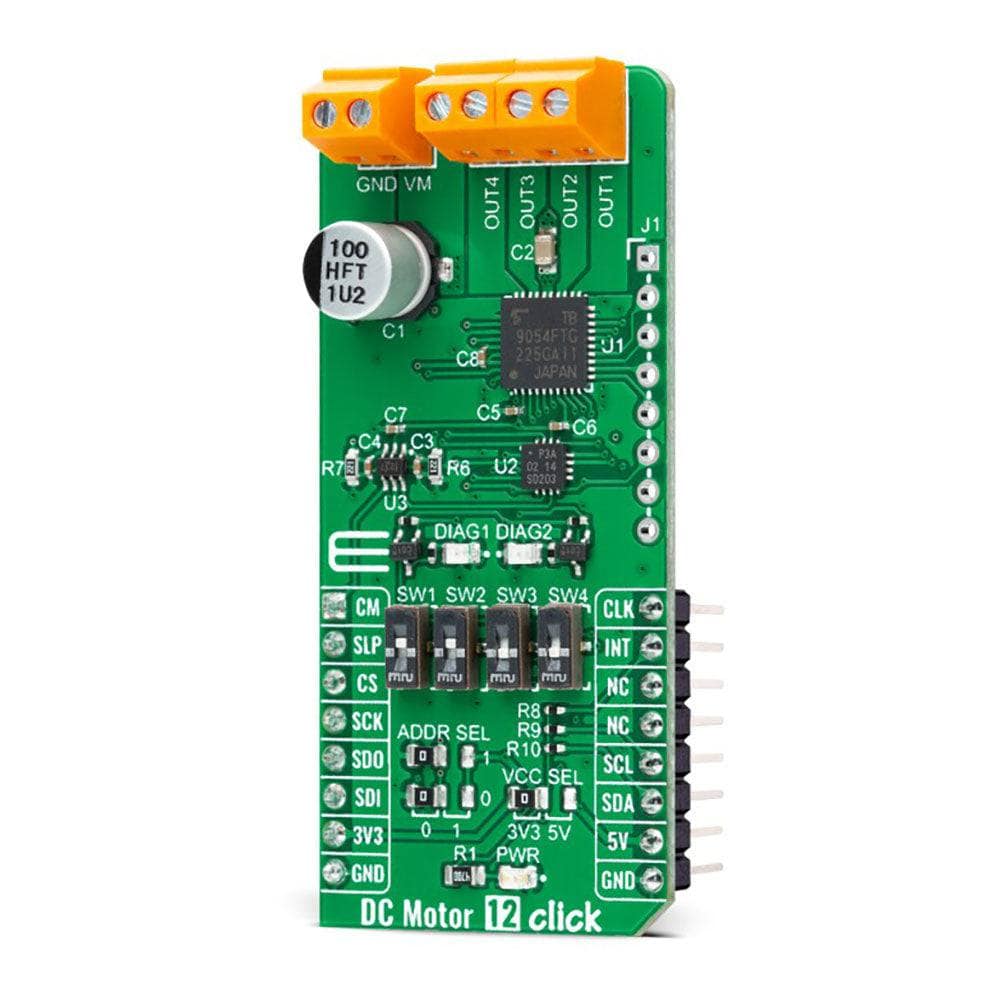
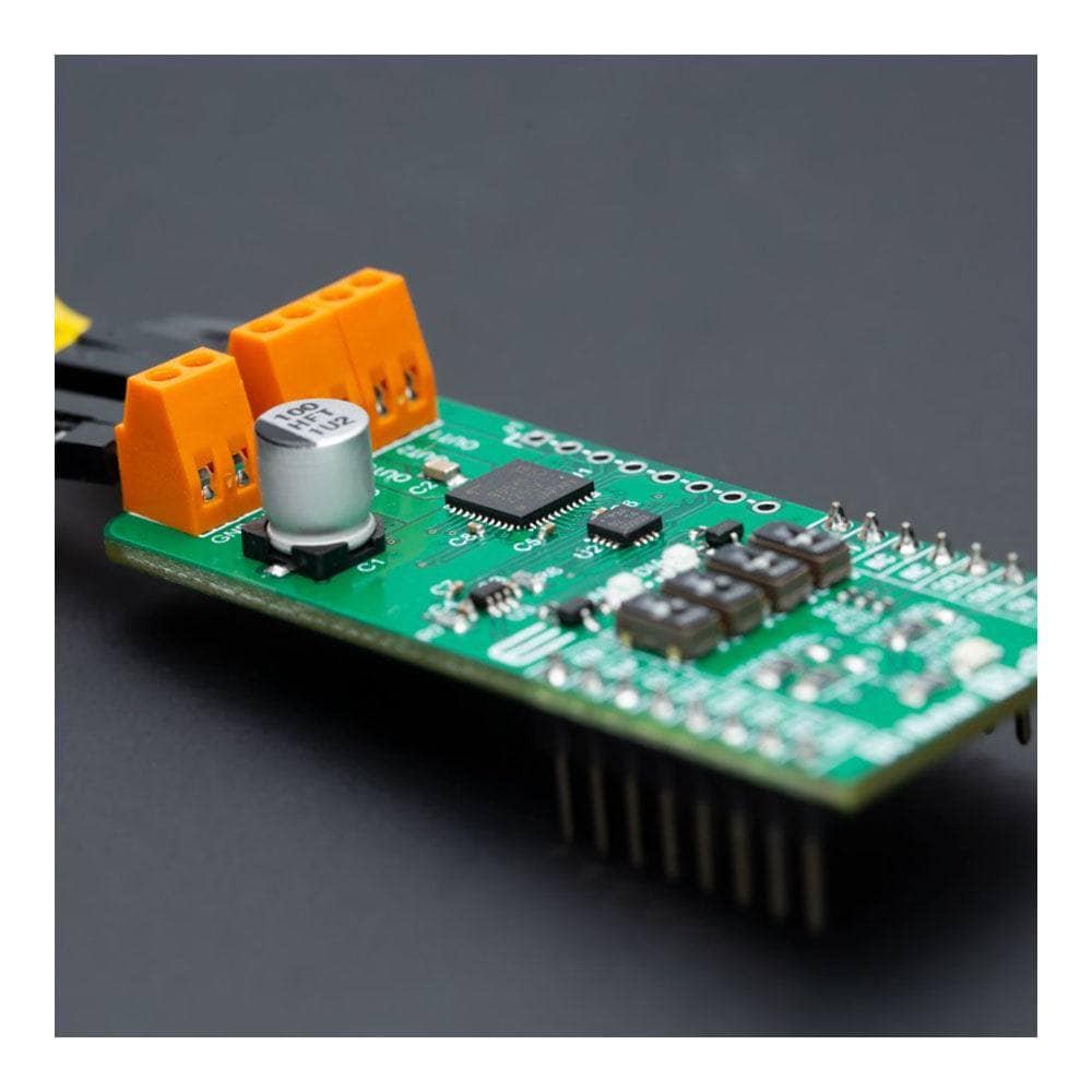
Das DC Motor 12 Click Board™ ist eine kompakte Zusatzplatine mit einem bürstenbehafteten Gleichstrommotortreiber. Diese Platine verfügt über den TB9054FTG, einen PWM-Typ, zweikanaligen H-Brücken-Bürsten-Gleichstrommotortreiber von Toshiba Semiconductor. Der TB9054FTG ist für einen Betriebsspannungsbereich von 4,5 V bis 28 V ausgelegt, wobei der Motor direkt über ein PWM-Signal oder eine SPI-Seriellschnittstelle gesteuert wird. Darüber hinaus ermöglicht dieser Treiber eine Dualkonfiguration mit zwei Motoren mit 5 A Nennstrom pro Kanal oder einem 10 A-Kanalantrieb im Parallelbetrieb. Es verfügt außerdem über vollständige Diagnose- und Schutzfunktionen, die einen robusten und zuverlässigen Betrieb unterstützen. Dieses Click Board™ eignet sich zum Antrieb von bürstenbehafteten Gleichstrommotoren in verschiedenen Automobilanwendungen wie der Steuerung der Drosselklappe, Motorventile, einklappbarer Türspiegel und Sitzheizung.
Das DC Motor 12 Click Board™ wird von einer mikroSDK-kompatiblen Bibliothek unterstützt, die Funktionen enthält, die die Softwareentwicklung vereinfachen. Dieses Click Board™ ist ein gründlich getestetes Produkt und kann auf einem System verwendet werden, das mit der mikroBUS™-Buchse ausgestattet ist.
How Does The DC Motor 12 Click Board™ Work?
The DC Motor 12 Click Board™ is based on the TB9054FTG, a dual-channel, H-bridge, brushed DC motor driver from Toshiba Semiconductor. The TB9054FTG allows a dual configuration with two motors with 5A current ratings per channel or one 10A channel drive in a Parallel mode of operation. It is also rated for an operating voltage range from 4.5V to 28V, with the motor controlled directly through an SPI serial interface or PWM signal from an unpopulated header. The PWM control with low on-resistance enables highly efficient motor drive output, ensuring reliable operation for highly competitive automotive applications.
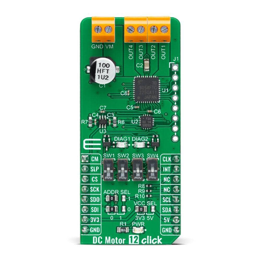
Besides the SPI communication, several GPIO pins connected to the mikroBUS™ socket pins are also used to control the TB9054FTG associated with the PCA9538A I2C-configurable port expander, such as Sleep Mode pin and DC motor channels current monitor routed to the RST and AN pins (SLP and CM) of the mikroBUS™ socket. The PCA9538A also allows choosing the least significant bit (LSB) of its I2C slave address by positioning SMD jumpers labelled as ADDR SEL to an appropriate position marked as 0 and 1, alongside its interrupt feature routed to the INT pin of the mikroBUS™ socket.
As mentioned, the DC Motor 12 Click Board™ supports double or single DC motor configuration. To select the motor control and operational modes, the corresponding switches on the board marked with SW1-SW4 are used. The first two represent the switches for motor control selection, more precisely, the choice of control directly by the PWM signal or through the SPI interface, while the second two represent the selection of the motor operational mode. There are four possible modes, i.e., Small Mode (two separated channels), Large Mode (two channels are connected and support one DC motor), Half Mode, and Prohibited Mode, where the channels are completely disabled.
The control and PWM signals can also be brought externally via the onboard header J1. In that case, the PWM1 and PWM2 pins specify forward, reverse, or brake modes for motor 1, and the PWM3 and PWM4 pins specify these modes for motor 2. The enable EN pins select the drive or stop mode for the motor. A broad range of configuration options for this driver, control, and mode selections, can be found in the attached datasheet. This Click board™ also has additional LEDs for anomaly indication. Suppose a state such as an overtemperature or overcurrent/under voltage is detected. In that case, such anomaly is indicated by red LEDs marked as DIAG1 and DIAG2 associated with the interrupt pin.
The DC Motor 12 Click Board™ supports an external power supply for the TB9054FTG, which can be connected to the input terminal labelled as VM and should be within the range of 4.5V to 28V, while the DC motor coils can be connected to the terminals labelled from OUT1 up to OUT4.
The DC Motor 12 Click Board™ can operate with both 3.3V and 5V logic voltage levels selected via the VCC SEL jumper. This way, it is allowed for both 3.3V and 5V capable MCUs to use the communication lines properly. However, the Click board™ comes equipped with a library containing easy-to-use functions and an example code that can be used, as a reference, for further development.
SPECIFICATIONS
Type | Brushed |
Applications | Can be used for automotive applications (AEC-Q100 Grade 1 qualified), such as control of the throttle valve, engine valves, retractable door mirrors, and seat heater |
On-board modules | TB9054FTG - brushed DC motor driver from Toshiba Semiconductor |
Key Features | Driver for one or two DC motors, direct PWM control or through SPI interface, selectable motor control functions and operational modes, Sleep mode and current monitoring, full protection and diagnostics, and more |
Interface | I2C,PWM,SPI |
Compatibility | mikroBUS |
Click board size | L (57.15 x 25.4 mm) |
Input Voltage | 3.3V,5V,External |
PINOUT DIAGRAM
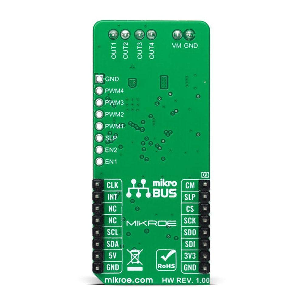
This table shows how the pinout of the DC Motor 12 Click Board™ corresponds to the pinout on the mikroBUS™ socket (the latter shown in the two middle columns).
Notes | Pin | Pin | Notes | ||||
---|---|---|---|---|---|---|---|
Channel Current Monitor | CM | 1 | AN | PWM | 16 | CLK | PWM Signal |
Sleep | SLP | 2 | RST | INT | 15 | INT | Interrupt |
SPI Chip Select | CS | 3 | CS | RX | 14 | NC | |
SPI Clock | SCK | 4 | SCK | TX | 13 | NC | |
SPI Data OUT | SDO | 5 | MISO | SCL | 12 | SCL | I2C Clock |
SPI Data IN | SDI | 6 | MOSI | SDA | 11 | SDA | I2C Data |
Power Supply | 3.3V | 7 | 3.3V | 5V | 10 | 5V | Power Supply |
Ground | GND | 8 | GND | GND | 9 | GND | Ground |
ONBOARD SETTINGS AND INDICATORS
Label | Name | Default | Description |
---|---|---|---|
LD1 | PWR | - | Power LED Indicator |
LD2-LD3 | DIAG1-DIAG2 | - | Diagnostic LED Indicators |
JP1 | VCC SEL | Left | Logic Level Voltage Selection 3V3/5V: Left position 3V3, Right position 5V |
JP2-JP3 | ADDR SEL | Left | I2C Address Selection 0/1: Left position 0, Right position 1 |
J1 | J1 | Unpopulated | External PWM/Control Signals Header |
SW1-SW2 | SW1-SW2 | Up | Motor Control Selection |
SW3-SW4 | SW3-SW4 | Down | Mode Selection |
DC MOTOR 12 CLICK ELECTRICAL SPECIFICATIONS
Description | Min | Typ | Max | Unit |
---|---|---|---|---|
Supply Voltage | 3.3 | - | 5 | V |
External Supply Voltage | 4.5 | - | 28 | V |
Output Current | 5 | 6.5 | 10 | A |
Operating Temperature Range | -40 | +25 | +125 | °C |
Software Support
We provide a library for the DC Motor 12 Click Board™ as well as a demo application (example), developed using MikroE compilers. The demo can run on all the main MikroE development boards.
The package can be downloaded/installed directly from NECTO Studio The package Manager(recommended), downloaded from our LibStock™ or found on MikroE Github account.
Library Description
This library contains API for DC Motor 12 Click driver.
Key functions
-
dcmotor12_get_motor_current
DC Motor 12 get motor current function. -
dcmotor12_set_ch1_operation_mode
DC Motor 12 set ch1 operation mode function. -
dcmotor12_set_cm_sel_pin
DC Motor 12 set cm sel pin function.
Example Description
This example demonstrates the use of the DC Motor 12 Click Board™ by controlling the speed of DC motor over PWM duty cycle as well as displaying the motor current consumption.
void application_task ( void )
{
if ( DCMOTOR12_OK == dcmotor12_set_ch1_operation_mode ( &dcmotor12, DCMOTOR12_MODE_OUTPUT_OFF ) )
{
log_printf ( &logger, " MODE: OFFrn" );
Delay_ms ( 3000 );
}
if ( DCMOTOR12_OK == dcmotor12_set_ch1_operation_mode ( &dcmotor12, DCMOTOR12_MODE_FORWARD ) )
{
dcmotor12_set_cm_sel_pin ( &dcmotor12, DCMOTOR12_PIN_LOW_LEVEL );
for ( uint16_t duty = 0; duty <= DCMOTOR12_CONFIG56_DUTY_PERIOD_MAX; duty += 100 )
{
float current;
log_printf ( &logger, " MODE: FORWARDrn" );
if ( DCMOTOR12_OK == dcmotor12_set_ch1_duty_period ( &dcmotor12, duty ) )
{
log_printf ( &logger, " Duty: %urn", duty );
}
if ( DCMOTOR12_OK == dcmotor12_get_motor_current ( &dcmotor12, ¤t ) )
{
log_printf ( &logger, " Current: %.3f Arnn", current );
}
Delay_ms ( 500 );
}
}
if ( DCMOTOR12_OK == dcmotor12_set_ch1_operation_mode ( &dcmotor12, DCMOTOR12_MODE_BRAKE ) )
{
log_printf ( &logger, " MODE: BRAKErn" );
Delay_ms ( 3000 );
}
if ( DCMOTOR12_OK == dcmotor12_set_ch1_operation_mode ( &dcmotor12, DCMOTOR12_MODE_REVERSE ) )
{
dcmotor12_set_cm_sel_pin ( &dcmotor12, DCMOTOR12_PIN_HIGH_LEVEL );
for ( uint16_t duty = 0; duty <= DCMOTOR12_CONFIG56_DUTY_PERIOD_MAX; duty += 100 )
{
float current;
log_printf ( &logger, " MODE: REVERSErn" );
if ( DCMOTOR12_OK == dcmotor12_set_ch1_duty_period ( &dcmotor12, duty ) )
{
log_printf ( &logger, " Duty: %urn", duty );
}
if ( DCMOTOR12_OK == dcmotor12_get_motor_current ( &dcmotor12, ¤t ) )
{
log_printf ( &logger, " Current: %.3f Arnn", current );
}
Delay_ms ( 500 );
}
}
}
The full application code, and ready to use projects can be installed directly from NECTO Studio The package Manager(recommended), downloaded from our LibStock™ or found on MikroE Github account.
Other MikroE Libraries used in the example:
- MikroSDK.Board
- MikroSDK.Log
- Click.DCMotor12
Additional Notes and Information
Depending on the development board you are using, you may need a USB UART Click Board™, USB UART 2 Click or RS232 Click to connect to your PC for development systems with no UART to USB interface available on the board. UART terminal is available in all MikroE compilers.
MIKROSDK
The DC Motor 12 Click Board™ is supported with mikroSDK – MikroElektronika’s Software Development Kit. mikroSDK should be downloaded from the LibStock™ and installed for the compiler you are using to ensure proper operation of mikroSDK compliant Click board™ demo applications.
Frequently Asked Questions
Have a Question?
Be the first to ask a question about this.