Zu Produktinformationen springen
1 von 7

Mikroelektronika d.o.o.

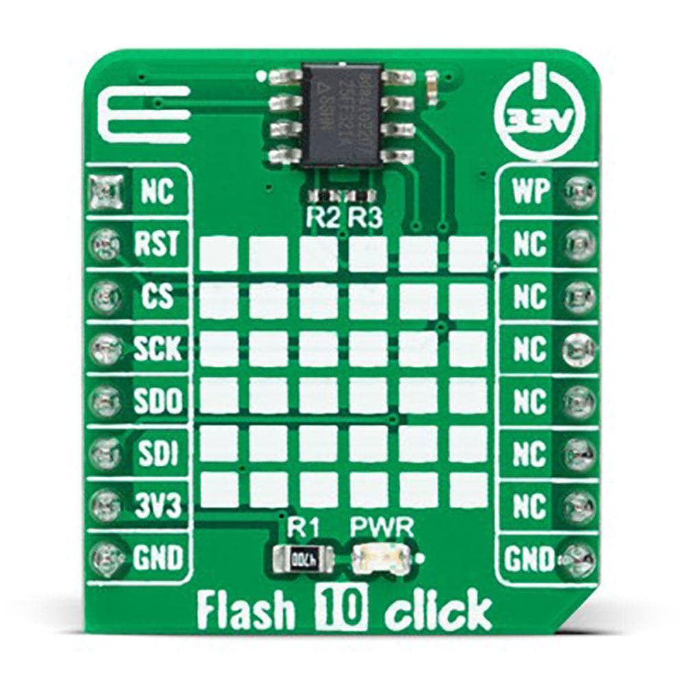
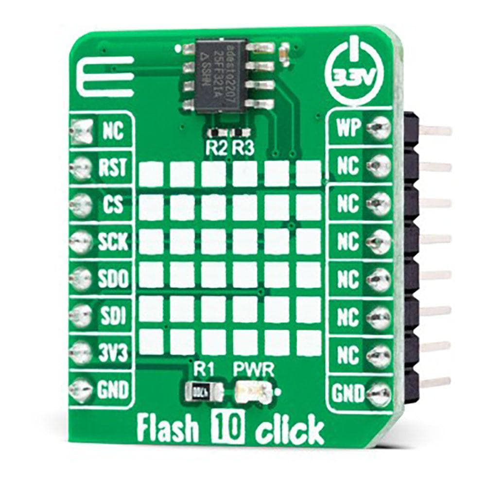
Flash 10 Click-Platine

Flash 10 Click-Platine

SKU: MIKROE-5289
Normaler Preis
€5,95 EUR ohne MwSt
Normaler Preis Verkaufspreis
€5,95 EUR ohne MwSt
Sale Ausverkauft
Versand wird beim Checkout berechnet
If no stock shown above, check availability
Vollständige Details anzeigen
} ] }

Key Features

32 mbit (16 x 2 mbit physischer block) flash-speicher, optimierte löscharchitektur für code- und datenspeicheranwendungen, flexibler nichtflüchtiger blockschutz, hohe leistung, schreibschutz, datenbeständigkeit und -aufbewahrung, geringer stromverbrauch und mehr
Basierend auf dem at25ff321a – serielle flash-speicherlösung von dialog semiconductor
Kann zur speicherung und datenübertragung in verbrauchergeräten, unternehmenssystemen und industriellen anwendungen verwendet werden
Mikrobus: spi- und qspi-schnittstellen

Overview

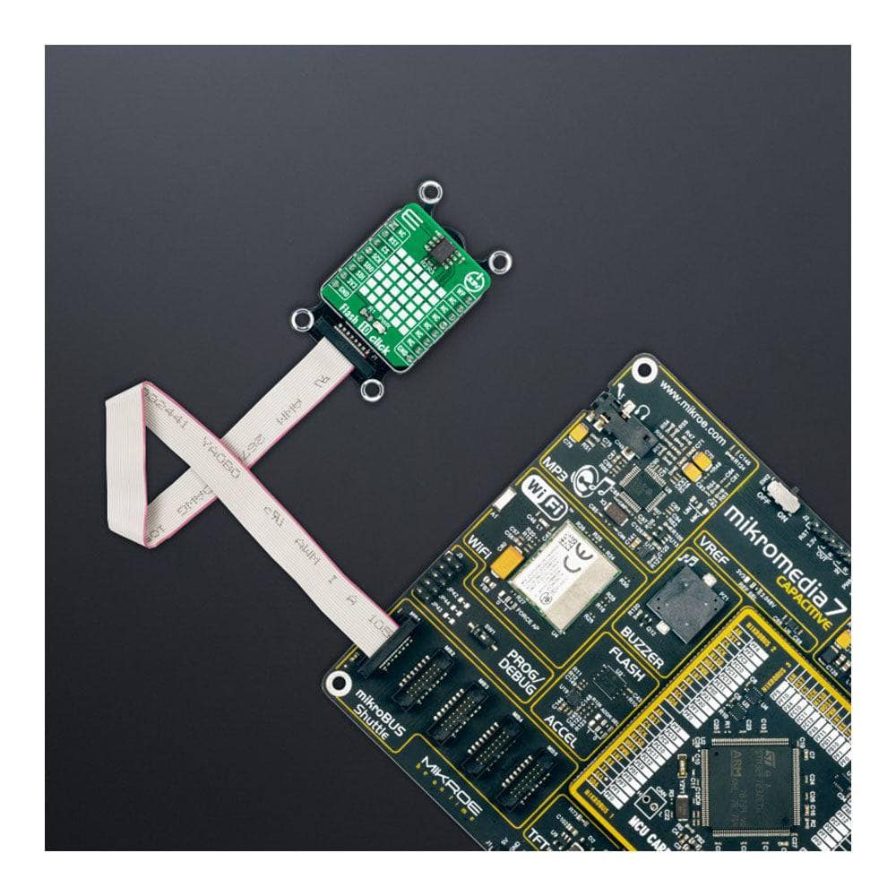
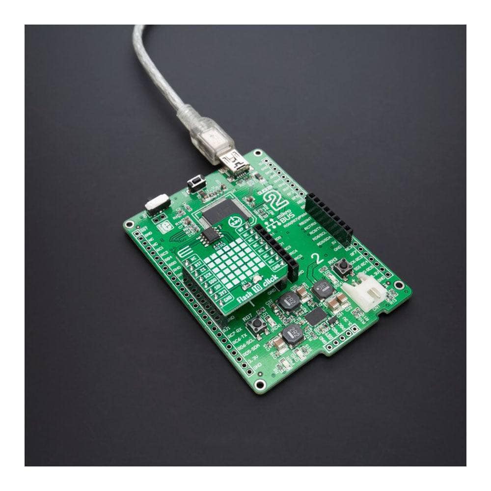
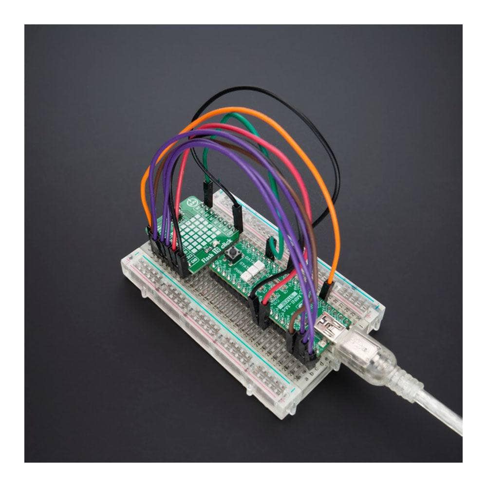
Das Flash 10 Click Board™ ist eine kompakte Zusatzplatine, die eine äußerst zuverlässige Speicherlösung darstellt. Diese Platine verfügt über das AT25FF321A, eine SPI-konfigurierbare serielle 32-Mbit-Flash-Speicherlösung (2Mx16) von Dialog Semiconductor. Das AT25FF321A ist eine ideale Lösung für Systeme, in denen Programmcode zur Ausführung vom Flash-Speicher in eingebetteten oder externen RAM (Code Shadow) gespiegelt wird und in denen kleine Datenmengen lokal im Flash-Speicher gespeichert und aktualisiert werden. Es verfügt über eine flexible und optimierte Löscharchitektur für Code- und Datenspeicheranwendungen, nichtflüchtigen Schutz und vier spezielle 128-Byte-OTP-Sicherheitsregister zum Speichern einer eindeutigen Geräte-ID und eines gesperrten Schlüsselspeichers. Dieser Speicher hält vielen Schreibzyklen stand (mindestens 100 KB) und hat eine Datenaufbewahrungsdauer von mehr als 20 Jahren. Dieses Click Board™ ist für die Speicherung und Datenübertragung in Verbrauchergeräten, Unternehmenssystemen und industriellen Anwendungen geeignet.

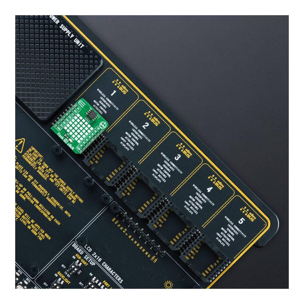
Das Flash 10 Click Board™ wird von einer mikroSDK-kompatiblen Bibliothek unterstützt, die Funktionen enthält, die die Softwareentwicklung vereinfachen. Dieses Click Board™ wird als vollständig getestetes Produkt geliefert und ist bereit für den Einsatz auf einem System, das mit der mikroBUS™-Buchse ausgestattet ist.


How Does The Flash 10 Click Board™ Work?

The Flash 10 Click Board™ as its foundation uses the AT25FF321A, a highly reliable serial Flash memory solution designed for use in a wide variety of high-volume consumer and connected applications from Dialog Semiconductor. The AT25FF321A is organized as a 32Mbit (16x2 Mbit physical block) Flash memory ideally suited for systems in which program code is shadowed from Flash memory into embedded or external RAM (code shadow) for execution and where small amounts of data are stored and updated locally in the Flash memory. The AT25FF321A specifies a minimum of 100.000 endurance cycles with data retention of a minimum of 20 years, giving it the capability to handle unlimited reads/writes to the memory.

Flash 10 Click inner

The AT25FF321A's erase block sizes are optimized to meet the needs of today's code and data storage applications, supporting flexible and optimized erase architecture for code and data storage applications (4kB, 32kB, and 64kB block erase operations) and a full-chip erase feature. The most efficient use of memory space can be achieved by optimizing the erase blocks' size. Also, the AT25FF321A contains four specialized 128-byte One-Time Programmable (OTP) security registers which can be used to store a unique device ID and locked key storage.

The Flash 10 Click Board™ communicates with MCU through a standard SPI interface supporting the two most common SPI modes, SPI Mode 0 and 3. Furthermore, this Click board™ provides additional hardware-controlled functions. The configurable Write Protection, marked as WP and routed on the PWM pin of the mikroBUS™ socket, protects all registers (including status and configuration) from write operations and must be held low to inhibit all the write operations to registers. When this pin is low, all memory and register writes are prohibited, and the address counter is not incremented.

Also, it is possible to use the Reset or Hold function through the RST pin of the mikroBUS™ socket, depending on the state of the HOLD/RESET bit 7 in Status Register 3. In the case of the Hold function, this pin temporarily pauses serial communication without deselecting or resetting the device, while in the case of the Reset feature, a low logic level on the RST pin puts the AT25FF321A into a Reset state.

The Flash 10 Click Board™ can be operated only with a 3.3V logic voltage level. The board must perform appropriate logic voltage level conversion before using MCUs with different logic levels. However, the Click board™ comes equipped with a library containing functions and an example code that can be used, as a reference, for further development.

SPECIFICATIONS


Type FLASH
Applications Can be used for storage and data transfer in consumer devices, enterprise systems, and industrial applications
On-board modules AT25FF321A - serial Flash memory solution from Dialog Semiconductor
Key Features 32Mbit (16x2Mbit physical block) flash memory, optimized erase architecture for code and data storage applications, flexible non-volatile block protection, high performance, write protection, data endurance and retention, low power consumption, and more
Interface QSPI,SPI
Compatibility mikroBUS
Click board size S (28.6 x 25.4 mm)
Input Voltage 3.3V


PINOUT DIAGRAM

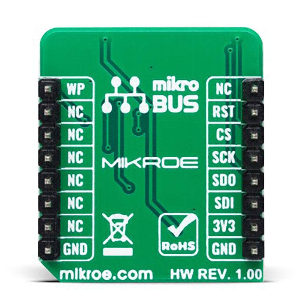
This table shows how the pinout of the Flash 10 Click Board™ corresponds to the pinout on the mikroBUS™ socket (the latter shown in the two middle columns).

Notes Pin Mikrobus logo.png Pin Notes
  NC 1 AN PWM 16 WP QSPI IO2 / Write Protection
QSPI IO3 / Reset RST 2 RST INT 15 NC  
SPI Chip Select CS 3 CS RX 14 NC  
SPI Clock SCK 4 SCK TX 13 NC  
QSPI IO1 / SPI Data OUT SDO 5 MISO SCL 12 NC  
QSPI IO0 / SPI Data IN SDI 6 MOSI SDA 11 NC  
Power Supply 3.3V 7 3.3V 5V 10 NC  
Ground GND 8 GND GND 9 GND Ground

ONBOARD SETTINGS AND INDICATORS

Label Name Default Description
LD1 PWR - Power LED Indicator

FLASH 10 CLICK ELECTRICAL SPECIFICATIONS

Description Min Typ Max Unit
Supply Voltage - 3.3 - V
Memory Size - - 32 Mbit
Write Endurance 100k - - Cycles
Data Retention 20 - - Years
Operating Temperature Range -40 +25 +85 °C


Frequently Asked Questions

Have a Question?

Be the first to ask a question about this.

Ask a Question

Customer Reviews

Be the first to write a review
0%
(0)
0%
(0)
0%
(0)
0%
(0)
0%
(0)