


Mikroelektronika d.o.o.
I2C MUX 6 Click-Platine
I2C MUX 6 Click-Platine
SKU: MIKROE-5168
Verfügbarkeit für Abholungen konnte nicht geladen werden


Key Features
Overview
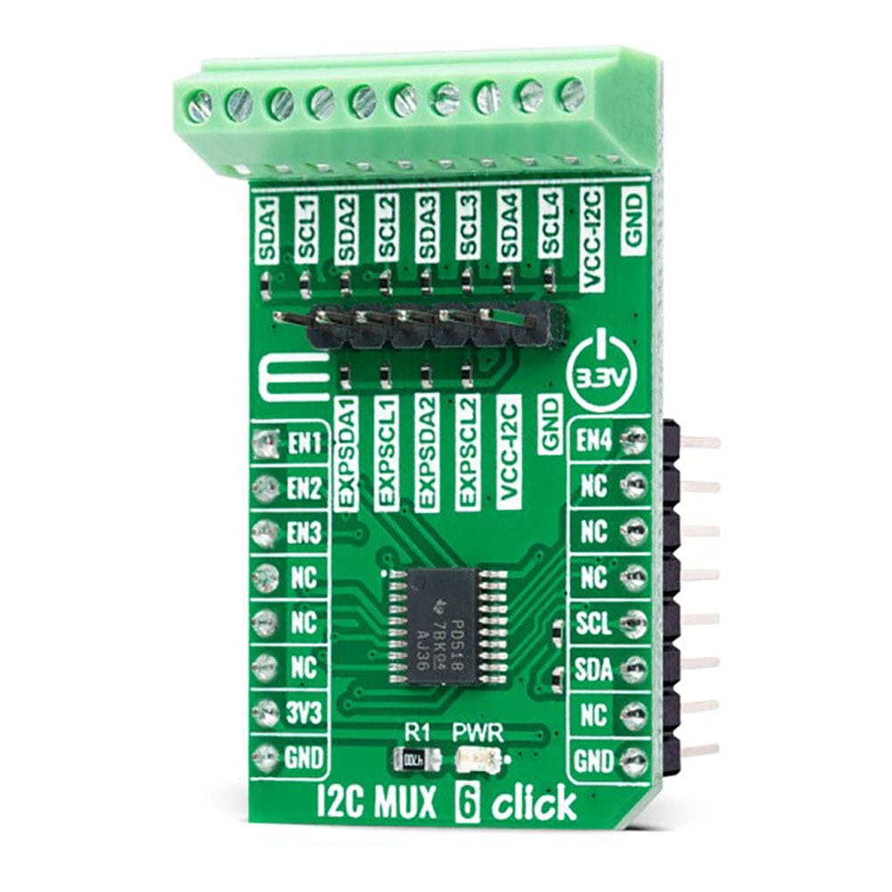
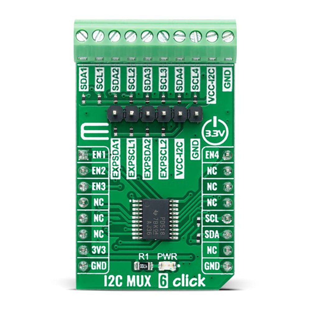
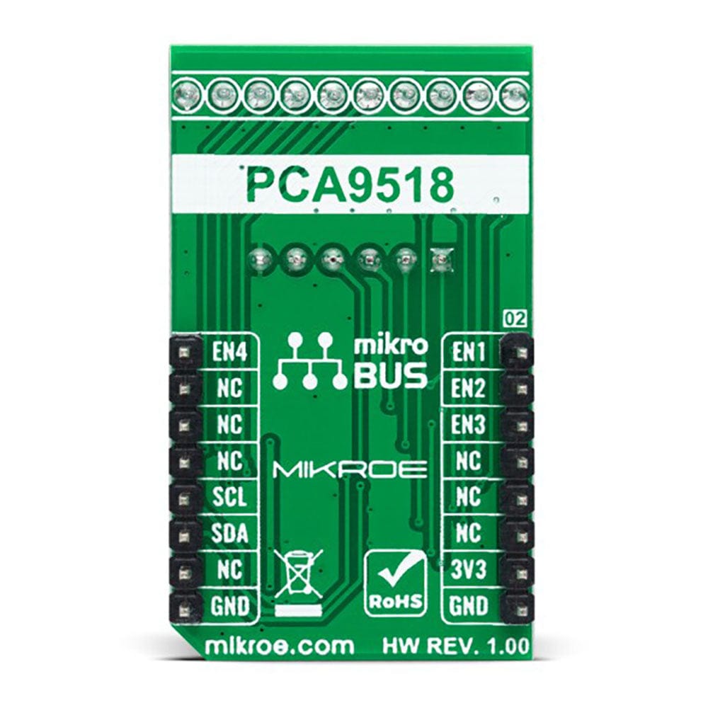
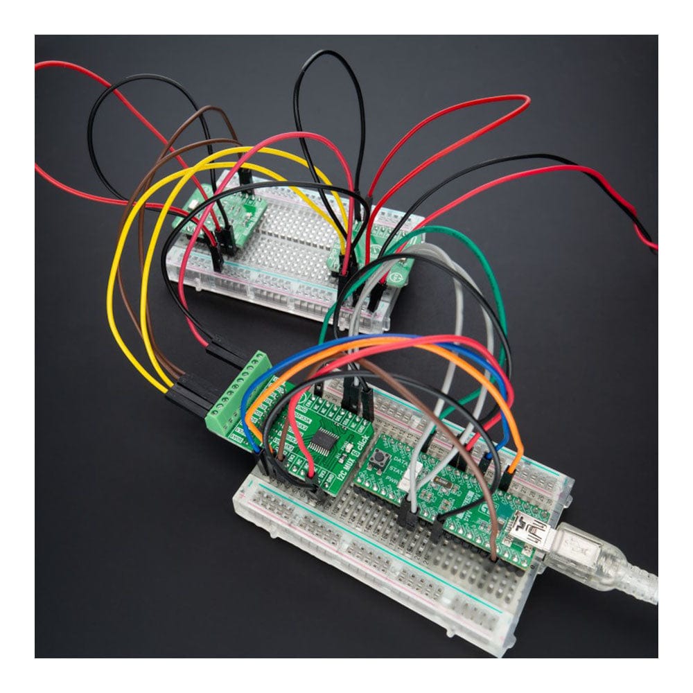
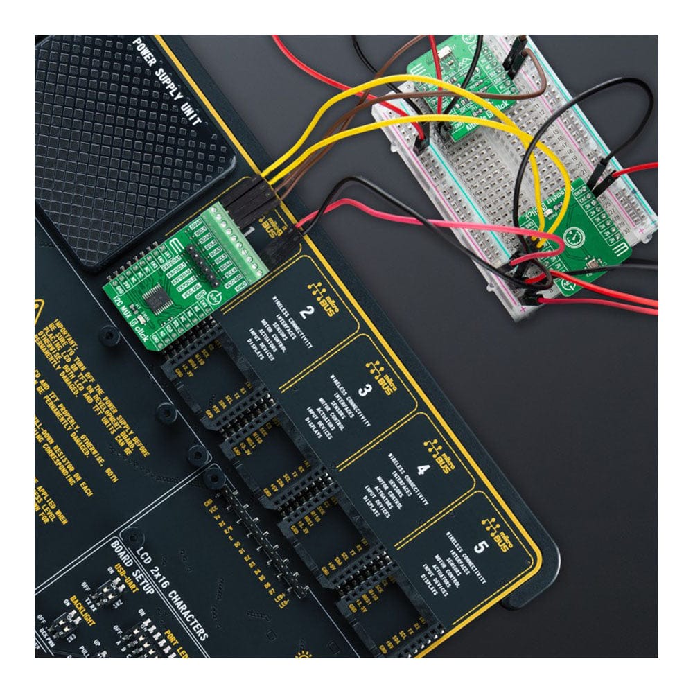
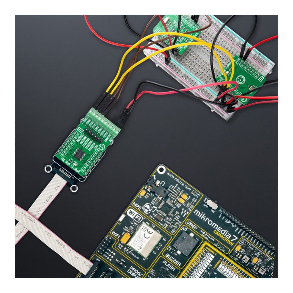
The I2C MUX 6 Click Board™ is a compact add-on board representing a bidirectional selector dedicated to I2C slave address conflicts applications. This board features the PCA9518, an expandable five-channel bidirectional buffer controlled by the I2C-bus from Texas Instruments. The PCA9518 overcomes the restriction of maximum bus capacitance by separating and buffering the I2C data (SDA) and clock (SCL) lines into multiple groups of 400pF I2C channels. It activates the desired channel via a given Enable pin and permits extension of the I2C-bus, through an onboard expansion header, by buffering both the data (SDA) and the clock (SCL) lines enabling virtually an unlimited number of buses of 400pF. This Click board™ is suitable for various industrial, medical, communications, and automotive applications.
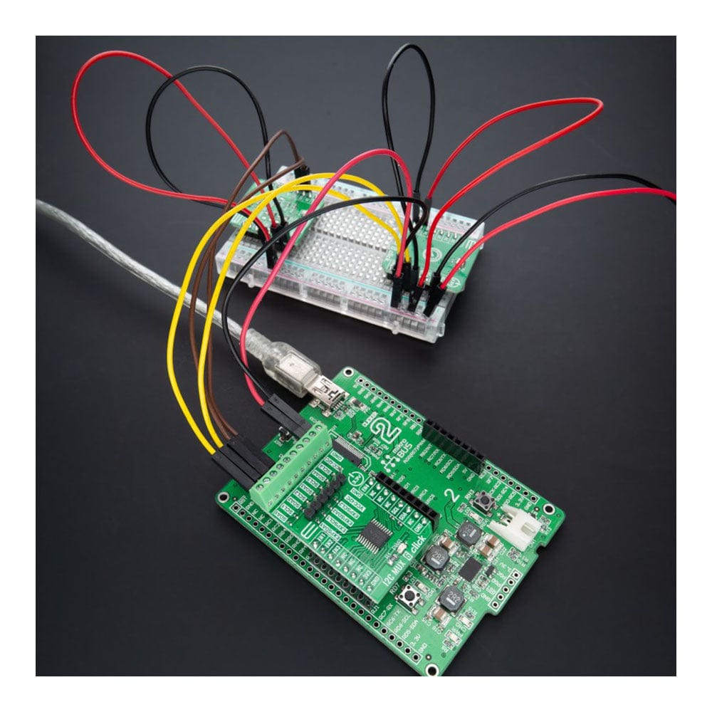
The I2C MUX 6 Click Board™ is supported by a mikroSDK compliant library, which includes functions that simplify software development. This Click board™ comes as a fully tested product, ready to be used on a system equipped with the mikroBUS™ socket.
Downloads
Das I2C MUX 6 Click Board™ ist eine kompakte Zusatzplatine, die einen bidirektionalen Selektor für Anwendungen mit I2C-Slave-Adresskonflikten darstellt. Diese Platine verfügt über den PCA9518, einen erweiterbaren bidirektionalen Fünfkanalpuffer, der vom I2C-Bus von Texas Instruments gesteuert wird. Der PCA9518 überwindet die Einschränkung der maximalen Buskapazität, indem er die I2C-Daten- (SDA) und Taktleitungen (SCL) in mehrere Gruppen von 400-pF-I2C-Kanälen trennt und puffert. Er aktiviert den gewünschten Kanal über einen bestimmten Enable-Pin und ermöglicht die Erweiterung des I2C-Busses über einen integrierten Erweiterungs-Header, indem er sowohl die Daten- (SDA) als auch die Taktleitungen (SCL) puffert und so praktisch eine unbegrenzte Anzahl von Bussen mit 400 pF ermöglicht. Dieses Click Board™ ist für verschiedene Anwendungen in den Bereichen Industrie, Medizin, Kommunikation und Automobil geeignet.
Das I2C MUX 6 Click Board™ wird von einer mikroSDK-kompatiblen Bibliothek unterstützt, die Funktionen enthält, die die Softwareentwicklung vereinfachen. Dieses Click Board™ wird als vollständig getestetes Produkt geliefert und ist bereit für den Einsatz auf einem System, das mit der mikroBUS™-Buchse ausgestattet ist.
| General Information | |
|---|---|
Part Number (SKU) |
MIKROE-5168
|
Manufacturer |
|
| Physical and Mechanical | |
Weight |
0.02 kg
|
| Other | |
EAN |
8606027388583
|
Frequently Asked Questions
Have a Question?
Be the first to ask a question about this.