


Mikroelektronika d.o.o.
Gyro 7 Click-Board
Gyro 7 Click-Board
SKU: MIKROE-5145
Verfügbarkeit für Abholungen konnte nicht geladen werden


Overview
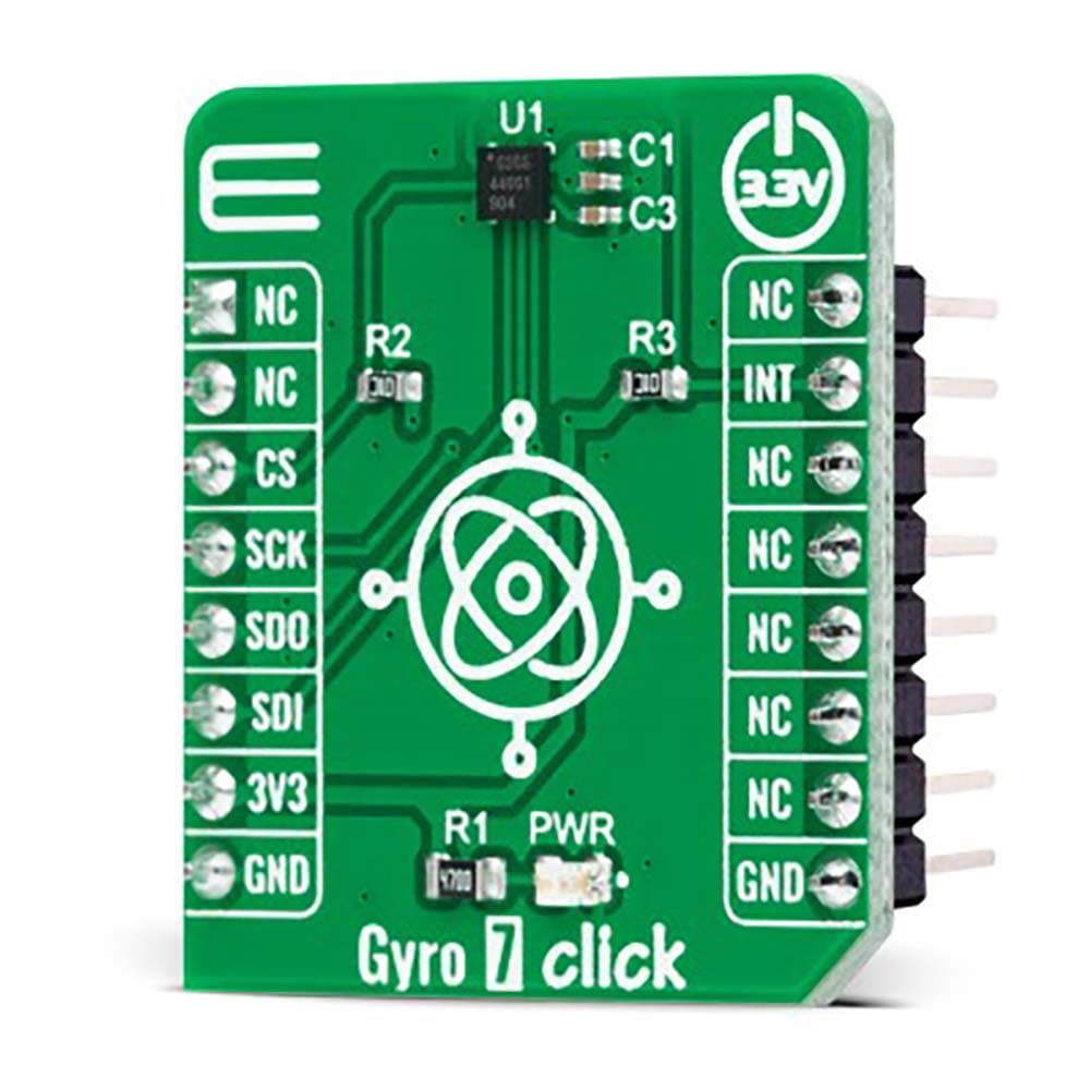
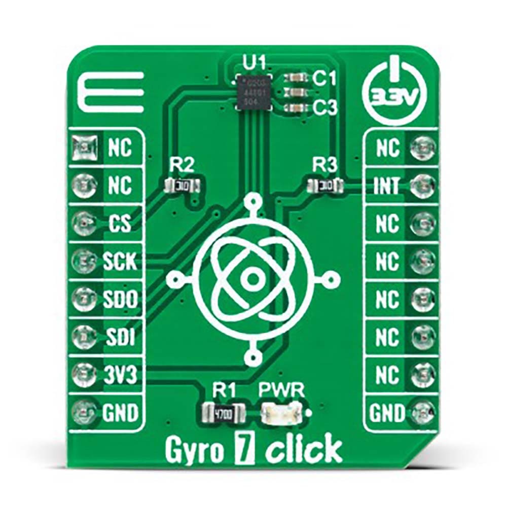
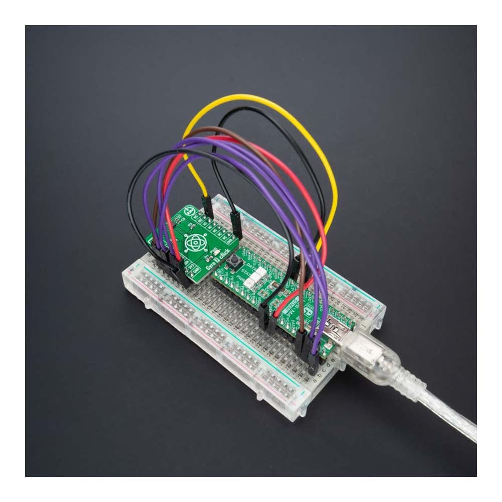
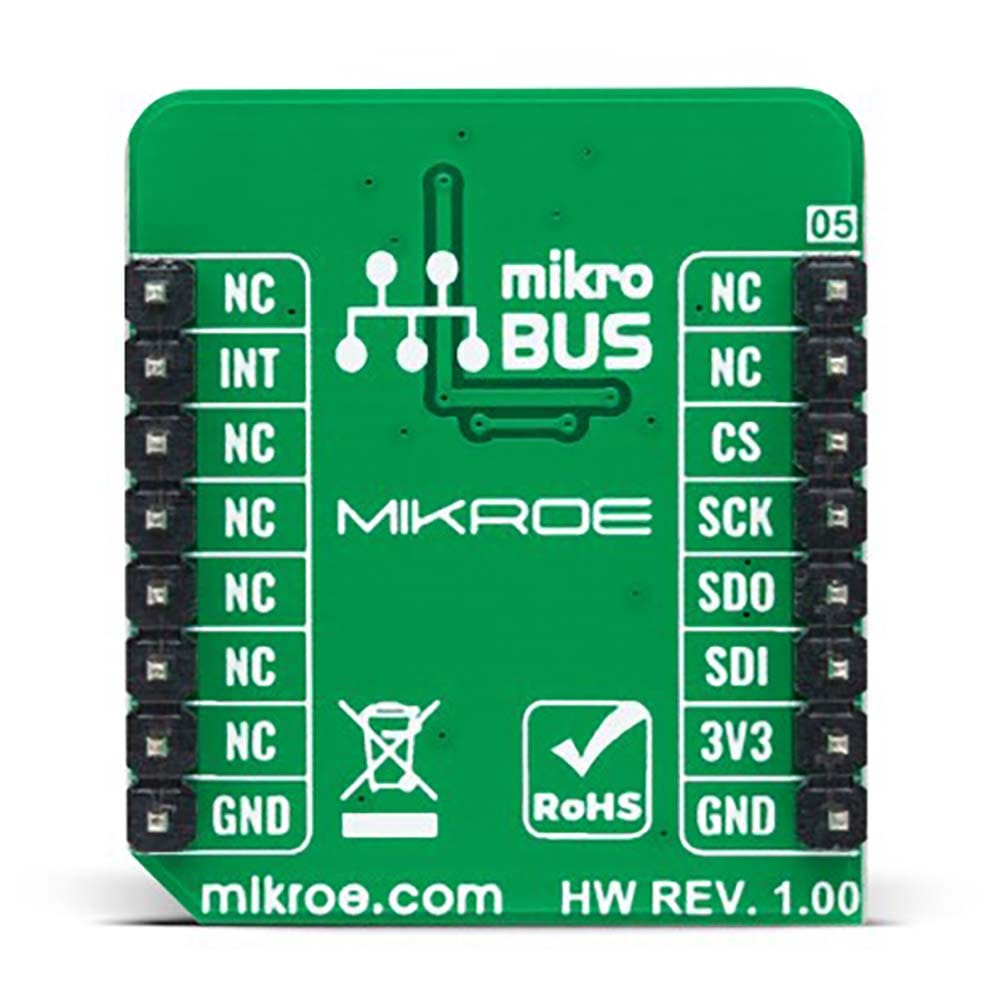
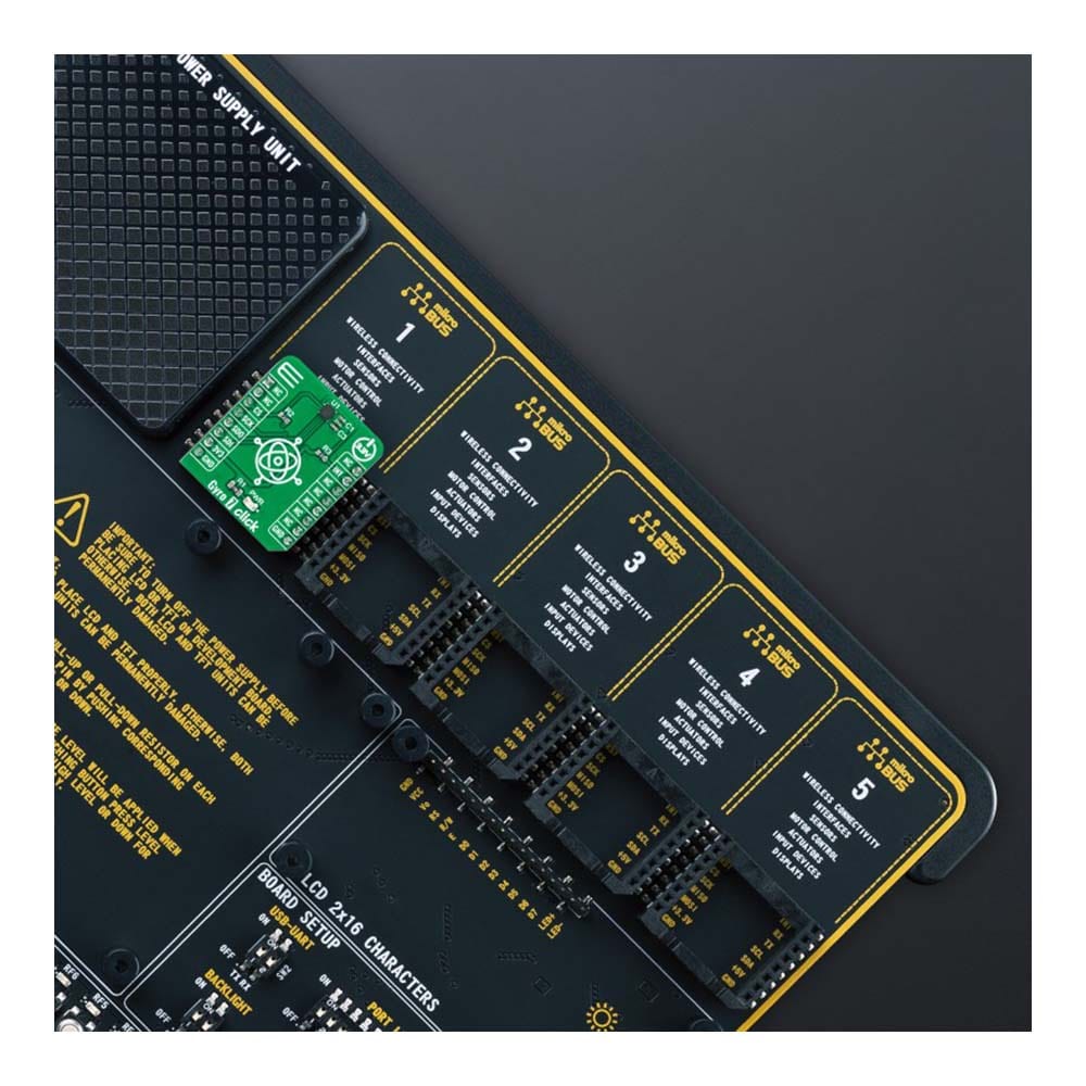
The Gyro 7 Click Board™ is a compact add-on board that contains a high-performance gyroscope. This board features the ICG-1020S, a dual-axis MEMS angular rate sensor (gyroscope) from TDK InvenSense. The ICG-1020S provides extremely low RMS noise as well as noise density. The high-resolution gyroscope supports a full-scale programmable range of ±46.5dps to ±374dps, a fast sample rate at up to 32kHz, an SPI serial interface, and extremely low power consumption. This Click board™ is designed for optical image stabilization (OIS) applications.
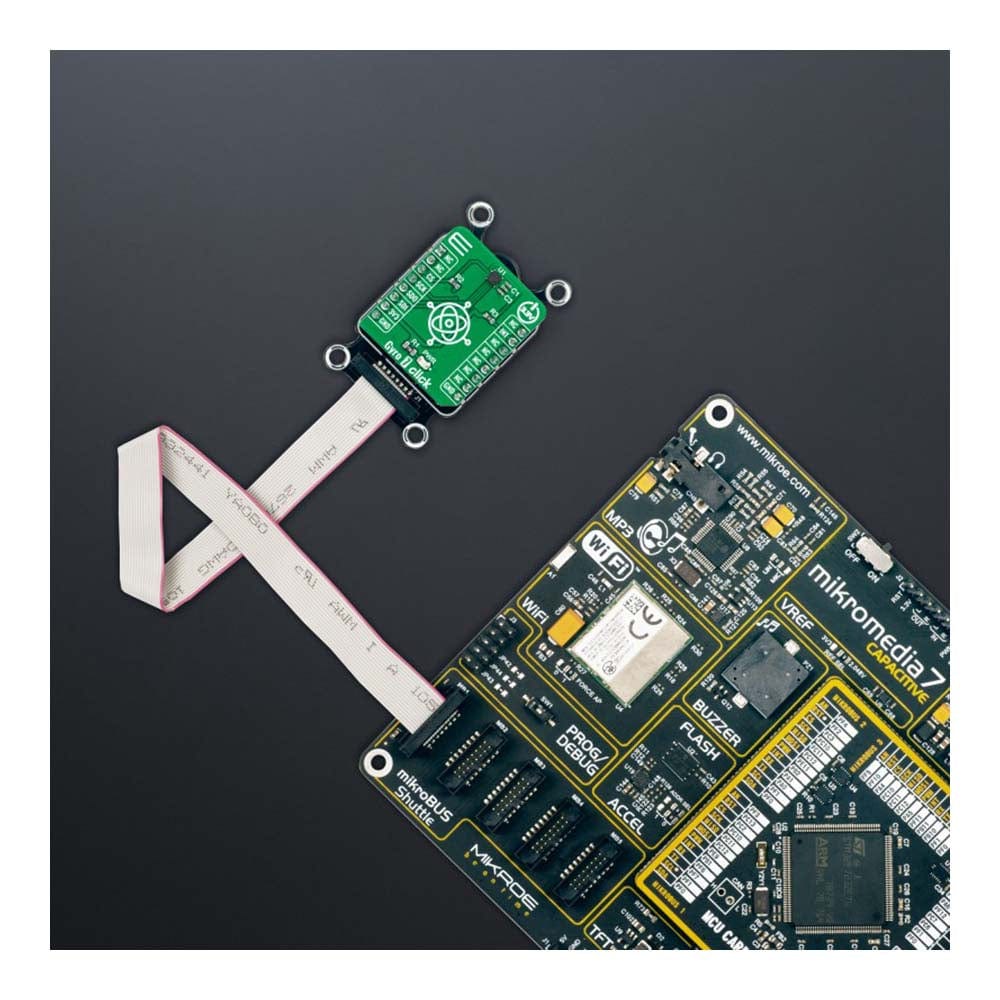
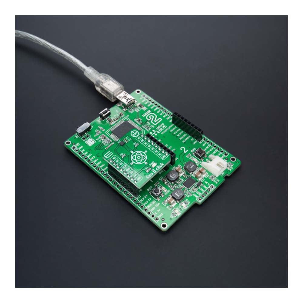
The Gyro 7 Click Board™ is supported by a mikroSDK compliant library, which includes functions that simplify software development. This Click board™ comes as a fully tested product, ready to be used on a system equipped with the mikroBUS™ socket.
Downloads
Das Gyro 7 Click Board™ ist eine kompakte Zusatzplatine, die ein Hochleistungsgyroskop enthält. Diese Platine verfügt über den ICG-1020S, einen zweiachsigen MEMS-Winkelgeschwindigkeitssensor (Gyroskop) von TDK InvenSense. Der ICG-1020S bietet extrem niedriges RMS-Rauschen sowie Rauschdichte. Das hochauflösende Gyroskop unterstützt einen voll programmierbaren Bereich von ±46,5 dps bis ±374 dps, eine schnelle Abtastrate von bis zu 32 kHz, eine serielle SPI-Schnittstelle und einen extrem niedrigen Stromverbrauch. Dieses Click Board™ wurde für Anwendungen zur optischen Bildstabilisierung (OIS) entwickelt.
Das Gyro 7 Click Board™ wird von einer mikroSDK-kompatiblen Bibliothek unterstützt, die Funktionen enthält, die die Softwareentwicklung vereinfachen. Dieses Click Board™ wird als vollständig getestetes Produkt geliefert und ist bereit für den Einsatz auf einem System, das mit der mikroBUS™-Buchse ausgestattet ist.
| General Information | |
|---|---|
Part Number (SKU) |
MIKROE-5145
|
Manufacturer |
|
| Physical and Mechanical | |
Weight |
0.02 kg
|
| Other | |
EAN |
8606027388828
|
Frequently Asked Questions
Have a Question?
Be the first to ask a question about this.