I2C MUX 7 Click-Platine
Overview
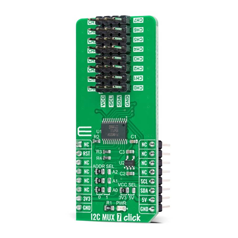
Das I2C MUX 7 Click Board™ ist eine kompakte Zusatzplatine, die einen bidirektionalen Selektor für Anwendungen mit I2C-Slave-Adresskonflikten darstellt. Diese Platine verfügt über den PI4MSD5V9547, einen oktalen bidirektionalen Übersetzungsmultiplexer, der über den I2C-Bus von Texas Instruments gesteuert wird. Es kann jeweils nur ein SCL/SDA-Kanal ausgewählt werden, der durch den Inhalt des programmierbaren Steuerregisters bestimmt wird. Die Platine wird mit angeschlossenem Kanal 0 eingeschaltet, was eine sofortige Kommunikation zwischen dem Master und nachgeschalteten Geräten auf diesem Kanal ermöglicht. Der PI4MSD5V9547 unterstützt auch Hot Insertion, hat einen niedrigen Standby-Strom und hat während der Einschaltsequenz keine Störungen. Dieses Click Board™ ist für eine Vielzahl von Anwendungen geeignet, von industriellen bis hin zu medizinischen, Kommunikations- und Automobilsystemen.
Das I2C MUX 7 Click Board™ wird von einer mikroSDK-kompatiblen Bibliothek unterstützt, die Funktionen enthält, die die Softwareentwicklung vereinfachen. Dieses Click Board™ wird als vollständig getestetes Produkt geliefert und ist bereit für den Einsatz auf einem System, das mit der mikroBUS™-Buchse ausgestattet ist.
How Does The I2C MUX 7 Click Board™ Work?
The I2C MUX 7 Click Board™ as its foundation uses the PI4MSD5V9547, a low voltage octal bidirectional translating multiplexer with an active-low reset input controlled through the I2C serial interface from Texas Instruments. The master SCL/SDA signal pair is directed to eight channels CH0-CH7, where only one SCL/SDA channel can be selected at a time, determined by the contents of the programmable control register. The board powers up with Channel 0 connected, allowing immediate communication between the Master and downstream devices on that channel.
The I2C MUX 7 Click Board™ includes a low dropout linear regulator AP2112 from Diodes Incorporated to provide the 1.8V supply voltage for the PI4MSD5V9547. When power is applied to IC, an internal Power-On Reset (POR) holds the PI4MSD5V9547 in a reset condition until the power supply reaches the POR voltage level. At this point, the reset condition is released, and the PI4MSD5V9547 registers and I2C-bus state machine are initialized to their default states (all zeroes), causing deselection of all channels.
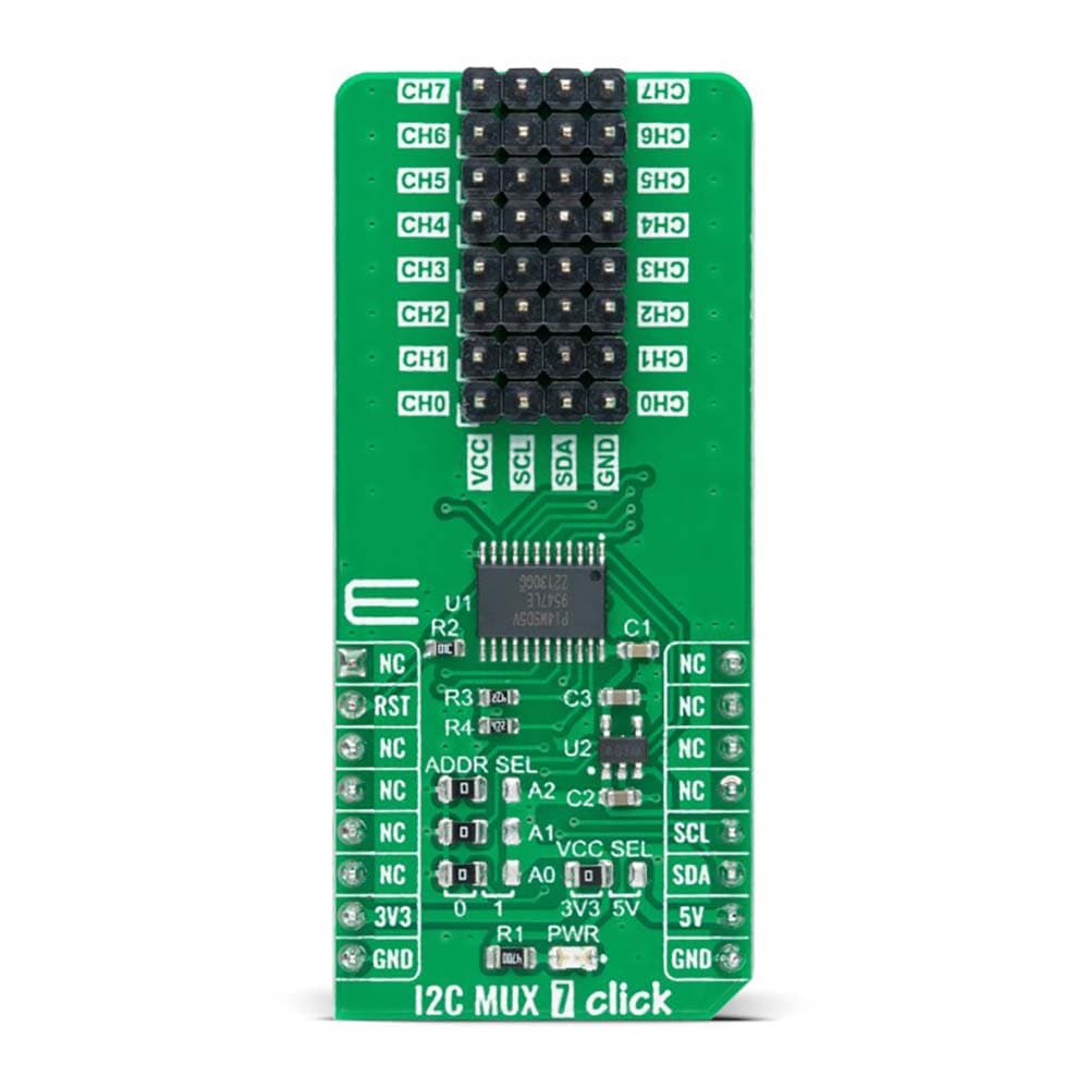
The I2C MUX 7 Click Board™ communicates with MCU using the standard I2C 2-Wire interface that supports Standard-Mode (100 kHz) and Fast-Mode (400 kHz) operation. The PI4MSD5V9547 has a 7-bit slave address with the first five MSBs fixed to 1110. The address pins A0, A1, and A2, are programmed by the user and determine the value of the last three LSBs of the slave address, which can be selected by onboard SMD jumpers labelled as ADDR SEL, allowing selection of the slave address LSBs. Alongside the internal Power-On Reset (POR) function, this board also has an active-low reset signal routed on the RST pin of the mikroBUS™ socket used to recover from a bus-fault condition. When this signal is asserted low, the PI4MSD5V9547 resets its registers alongside with I2C state machine and deselects all channels.
The I2C MUX 7 Click Board™ can operate with both 3.3V and 5V logic voltage levels selected via the VCC SEL jumper. This way, it is allowed for both 3.3V and 5V capable MCUs to use the communication lines properly. However, the Click board™ comes equipped with a library containing easy-to-use functions and an example code that can be used, as a reference, for further development.
SPECIFICATIONS
Type | I2C |
Applications | The I2C MUX 7 Click Board™ can be used for a wide range of applications from industrial to medical, communications, and automotive systems |
On-board modules | PI4MSD5V9547 - octal bidirectional translating multiplexer controlled by the I2C-bus from Texas Instruments |
Key Features | Low power consumption, reset feature, channel selection via I2C bus, Power-Up with one channel ON, no glich on Power-On, support hot insertion, and more |
Interface | I2C |
Compatibility | mikroBUS |
Click board size | L (57.15 x 25.4 mm) |
Input Voltage | 3.3V or 5V |
PINOUT DIAGRAM
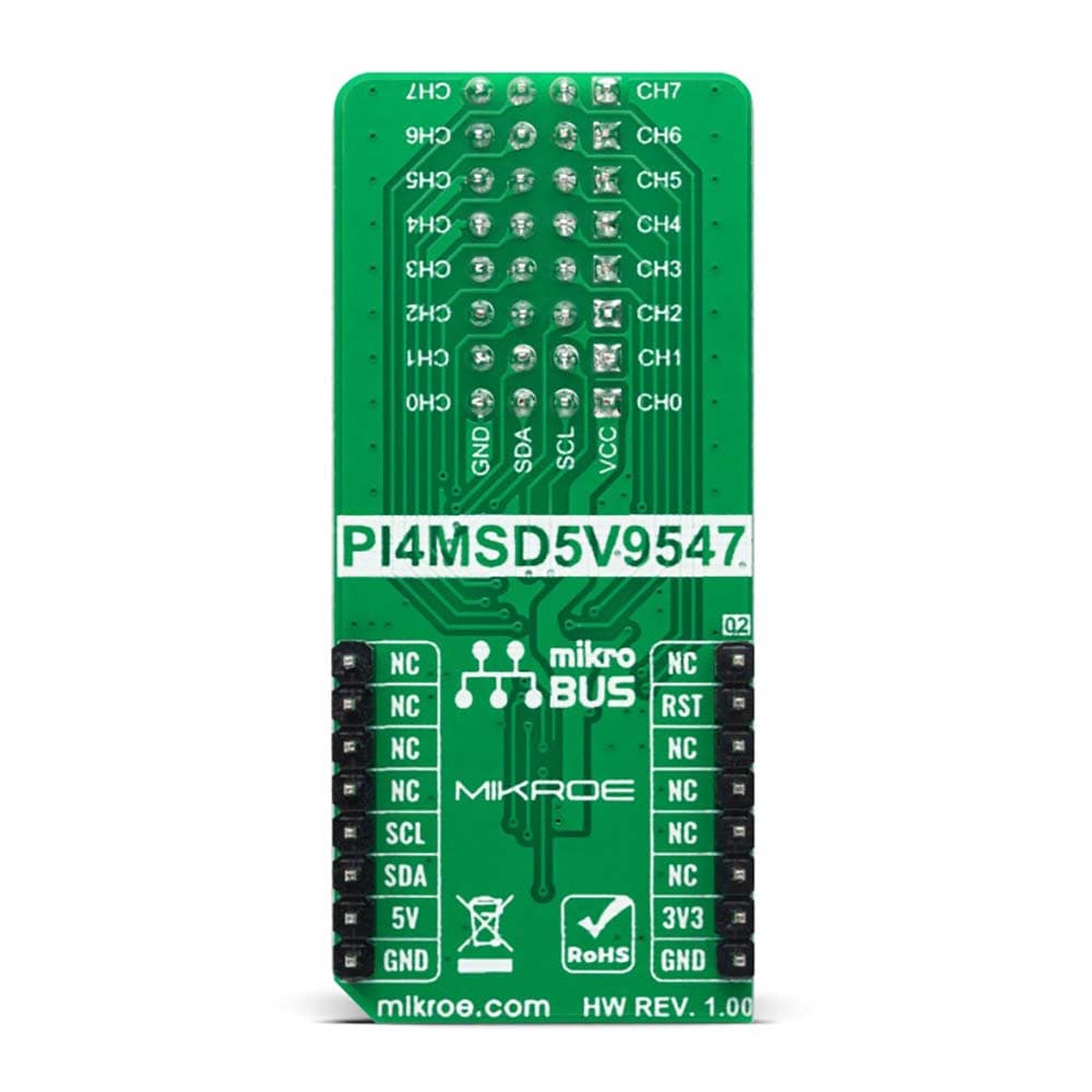
This table shows how the pinout of the I2C MUX 7 Click Board™ corresponds to the pinout on the mikroBUS™ socket (the latter shown in the two middle columns).
Notes | Pin | Pin | Notes | ||||
---|---|---|---|---|---|---|---|
NC | 1 | AN | PWM | 16 | NC | ||
Reset | RST | 2 | RST | INT | 15 | NC | |
NC | 3 | CS | RX | 14 | NC | ||
NC | 4 | SCK | TX | 13 | NC | ||
NC | 5 | MISO | SCL | 12 | SCL | I2C Clock | |
NC | 6 | MOSI | SDA | 11 | SDA | I2C Data | |
Power Supply | 3.3V | 7 | 3.3V | 5V | 10 | 5V | Power Supply |
Ground | GND | 8 | GND | GND | 9 | GND | Ground |
ONBOARD SETTINGS AND INDICATORS
Label | Name | Default | Description |
---|---|---|---|
LD1 | PWR | - | Power LED Indicator |
JP1 | VCC SEL | Left | Logic Level Voltage Selection 3V3/5V: Left position 3V3, Right position 5V |
JP2-JP4 | ADDR SEL | Left | I2C Address Selection 0/1: Left position 0, Right position 1 |
J1-J8 | CH0-CH7 | Populated | Output I2C Channel Pins |
I2C MUX 7 CLICK ELECTRICAL SPECIFICATIONS
Description | Min | Typ | Max | Unit |
---|---|---|---|---|
Supply Voltage | 3.3 | - | 5 | V |
ON Resistance | - | - | 70 | Ω |
Operating Temperature Range | -40 | +25 | +85 | °C |
We provide a library for the I2C MUX 7 Click Board™ as well as a demo application (example), developed using MikroElektronika compilers. The demo can run on all the main MikroElektronika development boards.
The package can be downloaded/installed directly from NECTO Studio The package Manager (recommended), downloaded from our LibStock™ or found on MikroE Github account.
Library Description
This library contains API for I2C MUX 7 Click Board™ driver.
Key functions
-
i2cmux7_set_channel
This function sets the desired channel active and configures its slave address. -
i2cmux7_read_channel
This function reads the currently selected channel value. -
i2cmux7_generic_read
This function reads a desired number of data bytes starting from the selected register by using I2C serial interface.
Example Description
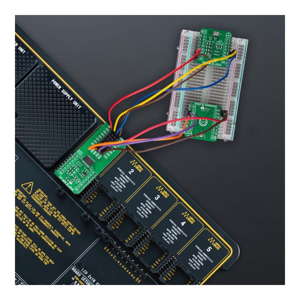
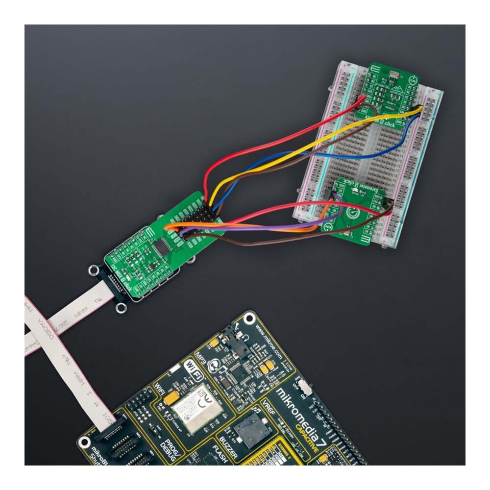
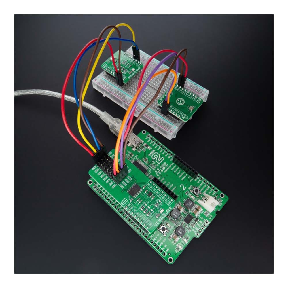
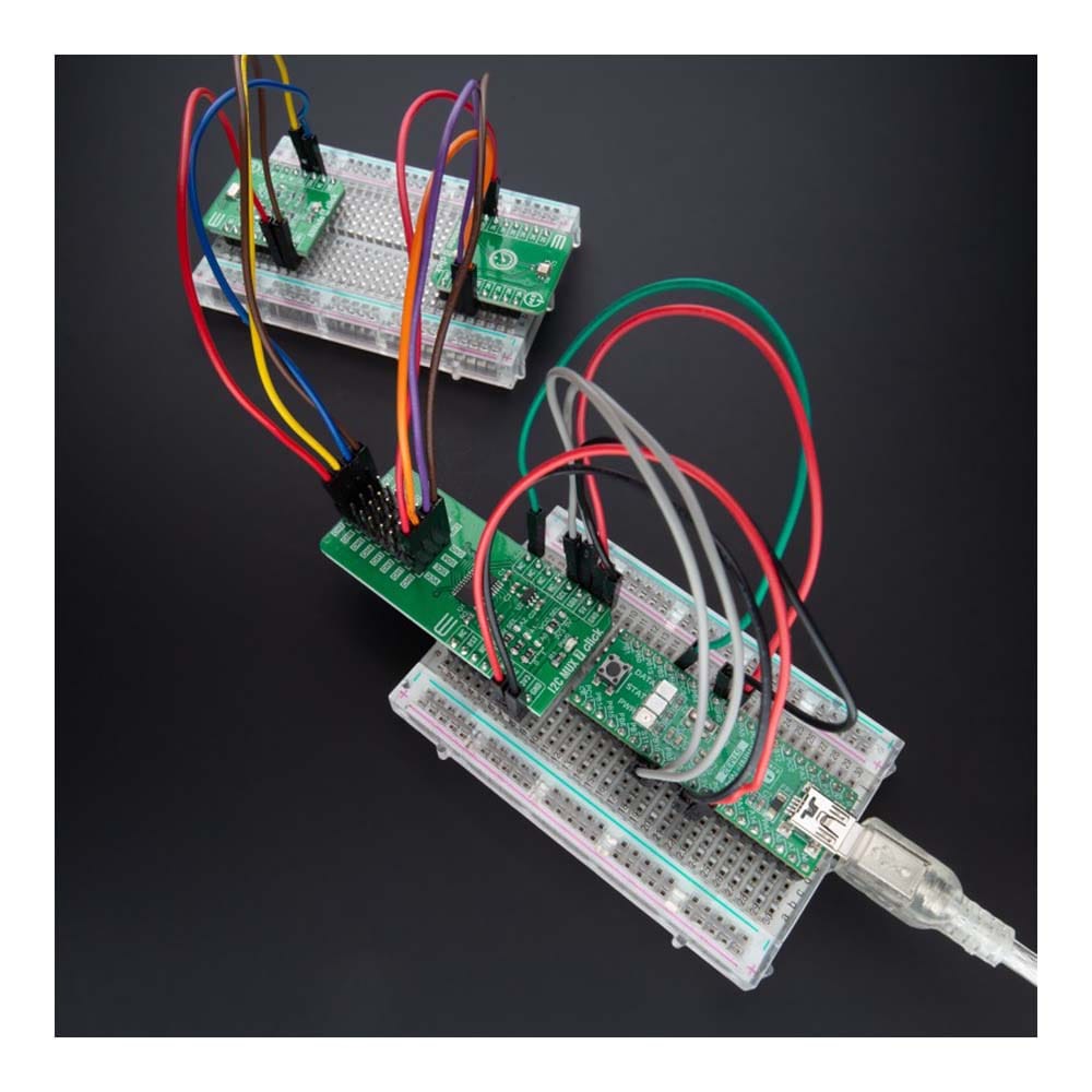
This example demonstrates the use of the I2C MUX 7 Click Board™ by reading the device ID of a 6DOF IMU 11 and Compass 3 click boards connected to the channels 0 and 7 respectfully.
void application_task ( void )
{
uint8_t channel, device_id;
if ( I2CMUX7_OK == i2cmux7_set_channel ( &i2cmux7, DEVICE0_POSITION, DEVICE0_SLAVE_ADDRESS ) )
{
if ( I2CMUX7_OK == i2cmux7_read_channel ( &i2cmux7, &channel ) )
{
log_printf( &logger, " --- Channel %u --- rn", ( uint16_t ) ( channel & I2CMUX7_CHANNEL_NUM_MASK ) );
}
if ( I2CMUX7_OK == i2cmux7_generic_read ( &i2cmux7, DEVICE0_REG_ID, &device_id, 1 ) )
{
log_printf( &logger, " %s - Device ID: 0x%.2X rnn", ( char * ) DEVICE0_NAME, ( uint16_t ) device_id );
}
Delay_ms( 1000 );
}
if ( I2CMUX7_OK == i2cmux7_set_channel ( &i2cmux7, DEVICE1_POSITION, DEVICE1_SLAVE_ADDRESS ) )
{
if ( I2CMUX7_OK == i2cmux7_read_channel ( &i2cmux7, &channel ) )
{
log_printf( &logger, " --- Channel %u --- rn", ( uint16_t ) ( channel & I2CMUX7_CHANNEL_NUM_MASK ) );
}
if ( I2CMUX7_OK == i2cmux7_generic_read ( &i2cmux7, DEVICE1_REG_ID, &device_id, 1 ) )
{
log_printf( &logger, " %s - Device ID: 0x%.2X rnn", ( char * ) DEVICE1_NAME, ( uint16_t ) device_id );
}
Delay_ms( 1000 );
}
}
The full application code, and ready to use projects can be installed directly from NECTO Studio The package Manager (recommended), downloaded from our LibStock™ or found on MikroE Github account.
Other MikroE Libraries used in the example:
- MikroSDK.Board
- MikroSDK.Log
- Click.I2CMUX7
Additional Notes and Information
Depending on the development board you are using, you may need USB UART click, USB UART 2 Click or RS232 Click to connect to your PC, for development systems with no UART to USB interface available on the board. UART terminal is available in all MikroElektronika compilers.
MIKROSDK
The I2C MUX 7 Click Board™ is supported with mikroSDK - MikroElektronika Software Development Kit. To ensure proper operation of mikroSDK compliant Click board™ demo applications, mikroSDK should be downloaded from the LibStock and installed for the compiler you are using.
Frequently Asked Questions
Have a Question?
Be the first to ask a question about this.