


Mikroelektronika d.o.o.
Bürstenloses 17 Click Board
Bürstenloses 17 Click Board
SKU: MIKROE-5000
Verfügbarkeit für Abholungen konnte nicht geladen werden


Key Features
Overview
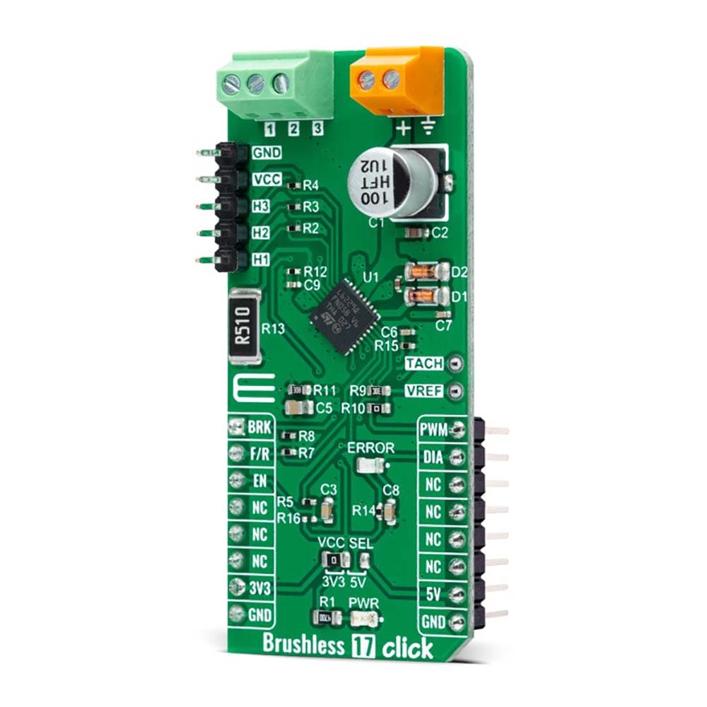
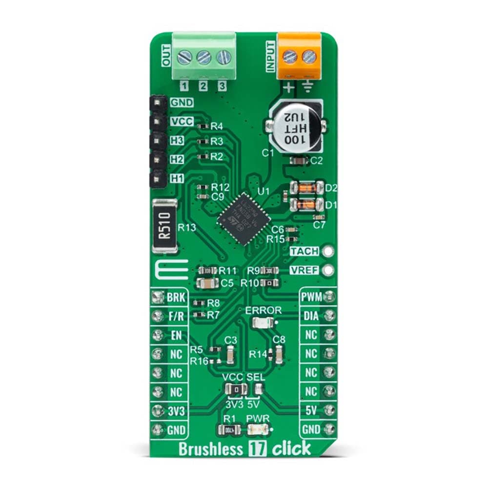
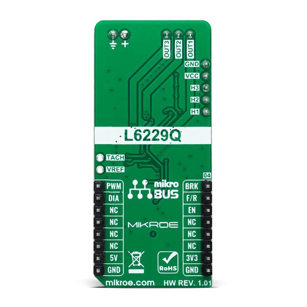
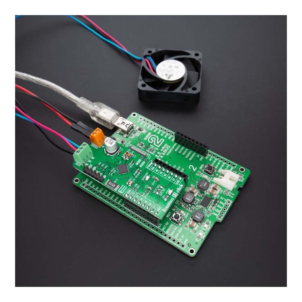
The Brushless 17 Click Board™ is a compact add-on board suitable for controlling brushless DC (BLDC) motors with any MCU. This board features the L6229Q, DMOS fully integrated three-phase BLDC motor driver with overcurrent protection from STMicroelectronics. This motor driver combines isolated DMOS power transistors with CMOS and bipolar circuits on the same chip, realized in BCD (Bipolar-CMOS-DMOS) multipower technology. It includes all the circuitry for a three-phase BLDC motor drive, including a three-phase DMOS bridge, a constant off-time PWM current controller, and the decoding logic for single-ended hall sensors that generate the required sequence for the power stage. This Click board™ makes the perfect solution for driving three-phase brushless DC motors with currents up to 1A DC.
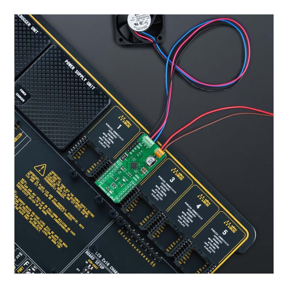
The Brushless 17 Click Board™ is supported by a mikroSDK compliant library, which includes functions that simplify software development. This Click board™ comes as a fully tested product, ready to be used on a system equipped with the mikroBUS™ socket.
Downloads
Das Brushless 17 Click Board™ ist eine kompakte Zusatzplatine, die sich zur Steuerung bürstenloser Gleichstrommotoren (BLDC) mit jedem MCU eignet. Diese Platine verfügt über den vollständig integrierten dreiphasigen BLDC-Motortreiber L6229Q, DMOS mit Überstromschutz von STMicroelectronics. Dieser Motortreiber kombiniert isolierte DMOS-Leistungstransistoren mit CMOS- und bipolaren Schaltkreisen auf demselben Chip, realisiert in BCD-Multipower-Technologie (Bipolar-CMOS-DMOS). Es umfasst die gesamte Schaltung für einen dreiphasigen BLDC-Motorantrieb, einschließlich einer dreiphasigen DMOS-Brücke, eines PWM-Stromreglers mit konstanter Ausschaltzeit und der Dekodierungslogik für einseitige Hallsensoren, die die erforderliche Sequenz für die Leistungsstufe erzeugen. Dieses Click Board™ ist die perfekte Lösung zum Antrieb dreiphasiger bürstenloser Gleichstrommotoren mit Strömen bis zu 1 A DC.
Das Brushless 17 Click Board™ wird von einer mikroSDK-kompatiblen Bibliothek unterstützt, die Funktionen enthält, die die Softwareentwicklung vereinfachen. Dieses Click Board™ wird als vollständig getestetes Produkt geliefert und ist bereit für den Einsatz auf einem System, das mit der mikroBUS™-Buchse ausgestattet ist.
| General Information | |
|---|---|
Part Number (SKU) |
MIKROE-5000
|
Manufacturer |
|
| Physical and Mechanical | |
Weight |
0.02 kg
|
| Other | |
EAN |
8606027388620
|
Frequently Asked Questions
Have a Question?
Be the first to ask a question about this.