


Mikroelektronika d.o.o.
CapSense 2 Click-Platine
CapSense 2 Click-Platine
SKU: MIKROE-4982
Verfügbarkeit für Abholungen konnte nicht geladen werden


Key Features
Overview
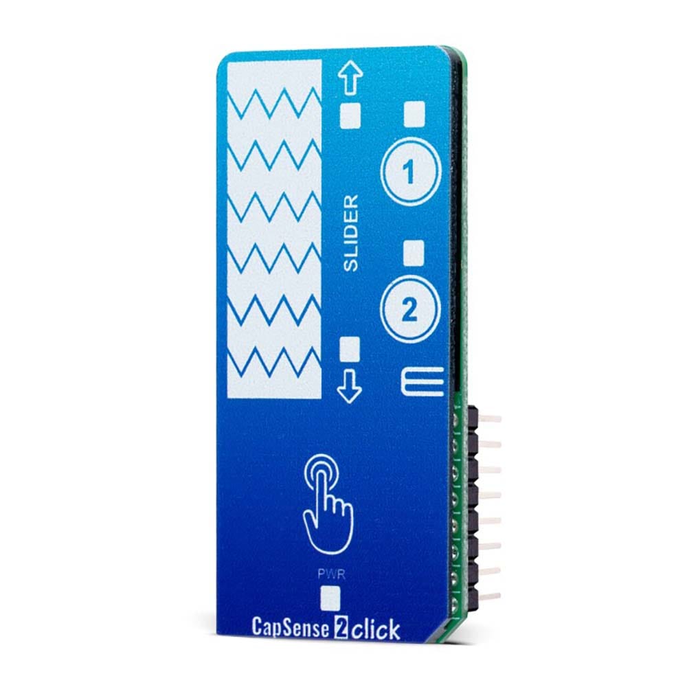
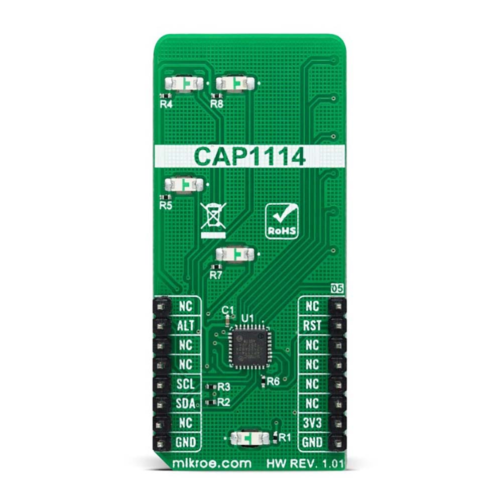
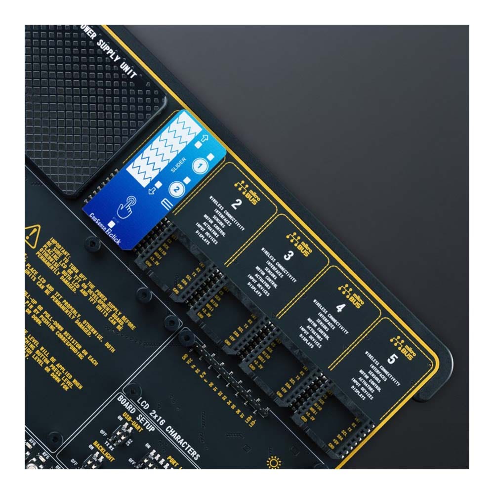
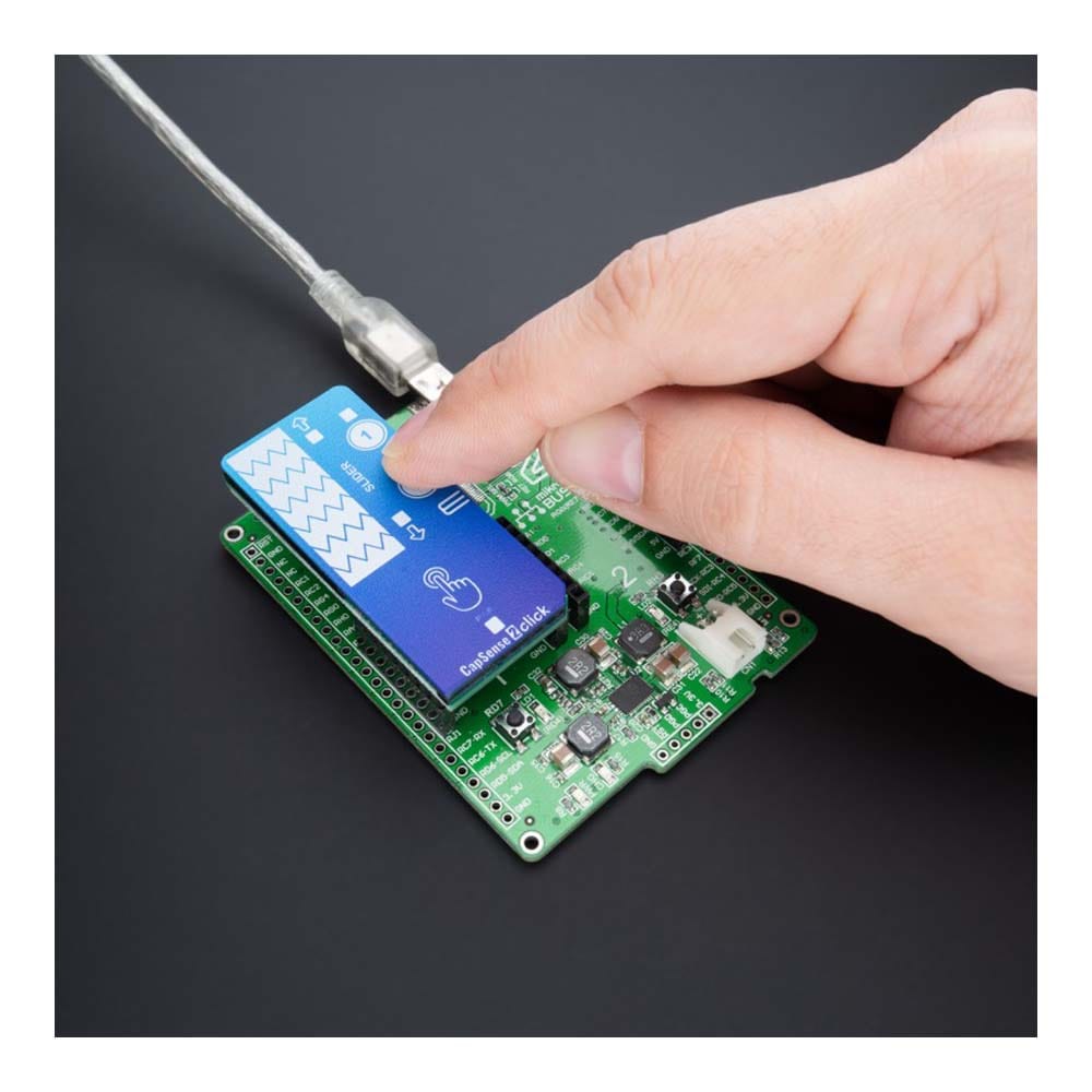
The CapSense 2 Click Board™ is a compact add-on board that easily integrates projected capacitive touch into user's applications. This board features the CAP1114, a multi-channel capacitive touch sensor that takes human body capacitance as an input and directly provides the real-time sensor information via the I2C serial interface from Microchip. This board contains capacitive sensing elements, a 7-segment slider, two buttons, and four LED indicators that visually detect the activation on some of these parts. This Click board™ offers reliable and accurate sensing for any application that uses capacitive touch sensing functions.
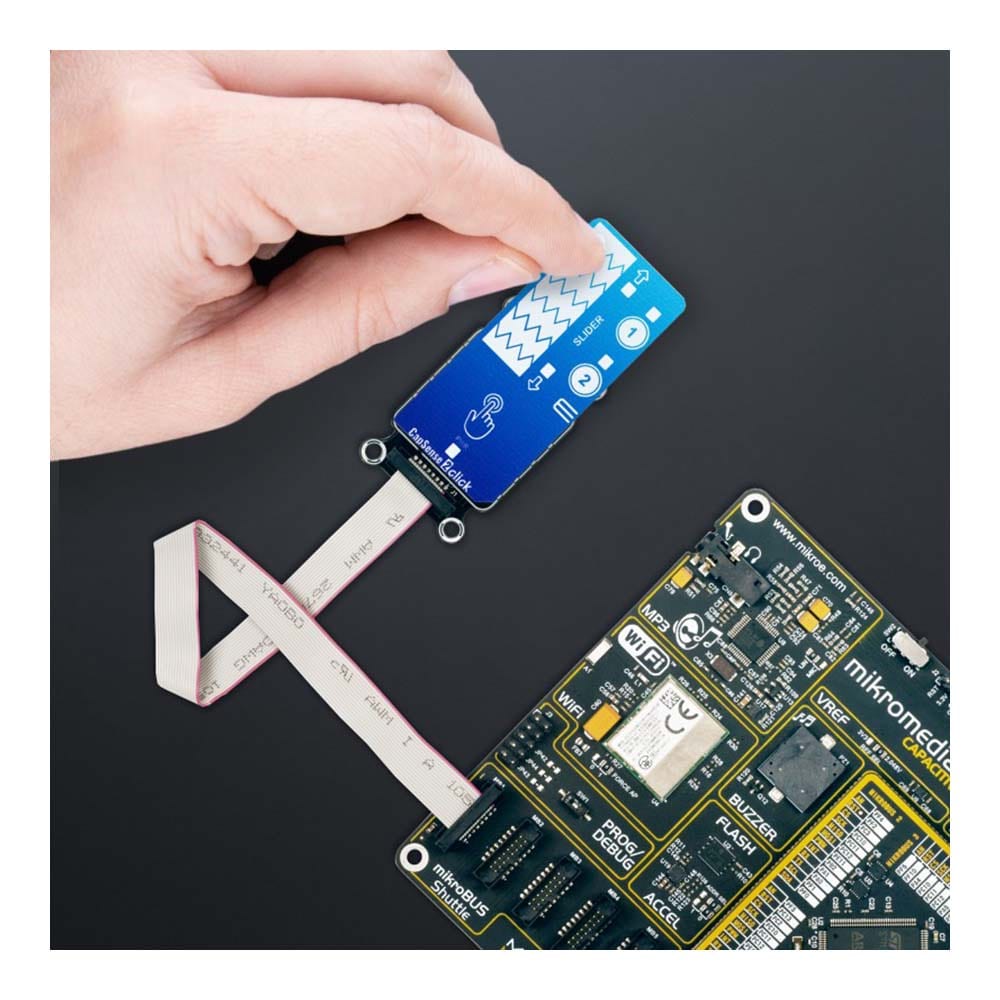
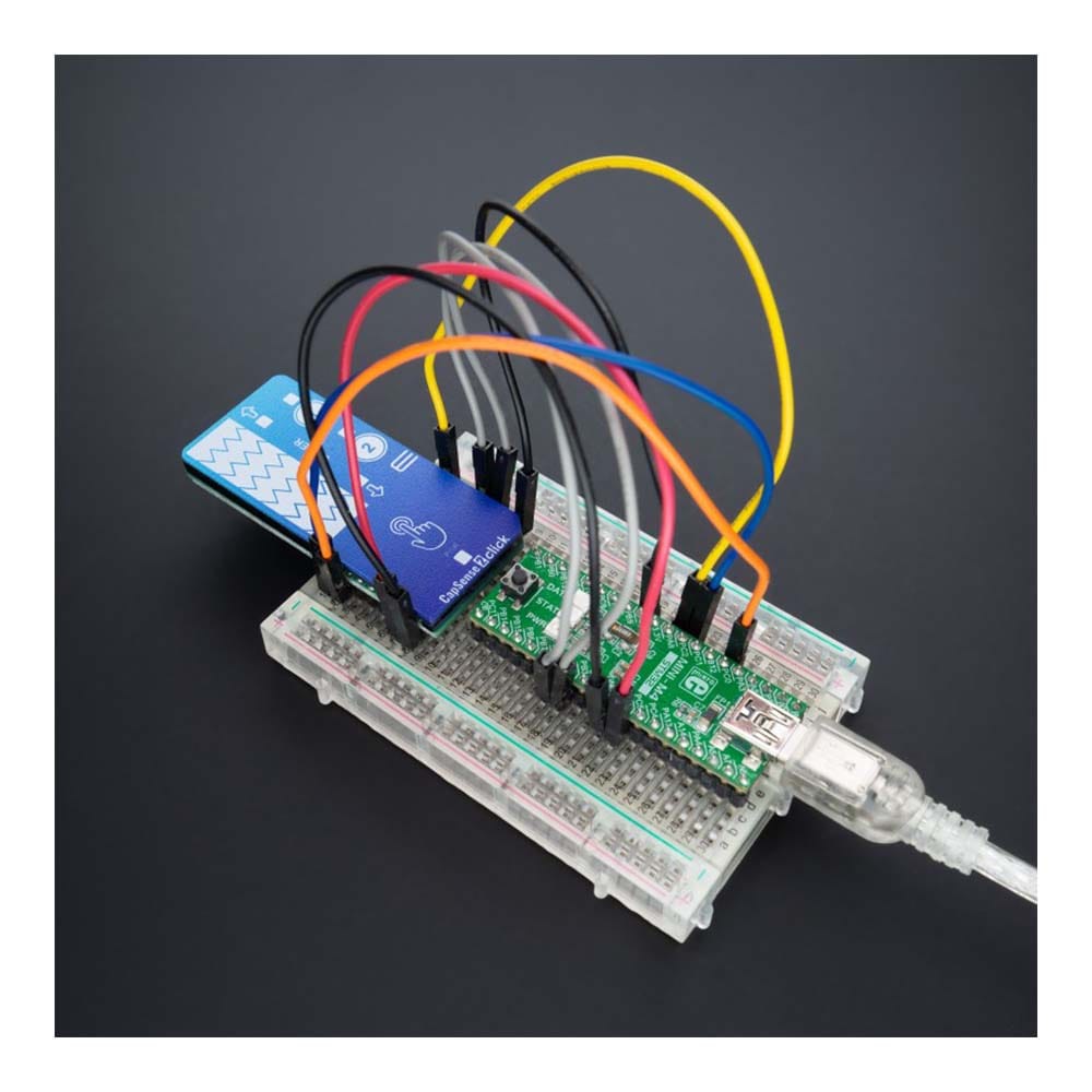
The CapSense 2 Click Board™ is supported by a mikroSDK compliant library, which includes functions that simplify software development. This Click board™ comes as a fully tested product, ready to be used on a system equipped with the mikroBUS™ socket.
Downloads
Das CapSense 2 Click Board™ ist eine kompakte Zusatzplatine, die projizierte kapazitive Berührungen problemlos in Benutzeranwendungen integriert. Diese Platine verfügt über den CAP1114, einen mehrkanaligen kapazitiven Berührungssensor, der die Kapazität des menschlichen Körpers als Eingabe verwendet und die Echtzeit-Sensorinformationen direkt über die serielle I2C-Schnittstelle von Microchip bereitstellt. Diese Platine enthält kapazitive Sensorelemente, einen 7-Segment-Schieberegler, zwei Tasten und vier LED-Anzeigen, die die Aktivierung einiger dieser Teile optisch erkennen. Dieses Click Board™ bietet zuverlässige und genaue Sensorik für jede Anwendung, die kapazitive Berührungssensorfunktionen verwendet.
Das CapSense 2 Click Board™ wird von einer mikroSDK-kompatiblen Bibliothek unterstützt, die Funktionen enthält, die die Softwareentwicklung vereinfachen. Dieses Click Board™ wird als vollständig getestetes Produkt geliefert und ist bereit für den Einsatz auf einem System, das mit der mikroBUS™-Buchse ausgestattet ist.
| General Information | |
|---|---|
Part Number (SKU) |
MIKROE-4982
|
Manufacturer |
|
| Physical and Mechanical | |
Weight |
0.03 kg
|
| Other | |
EAN |
8606027389290
|
Frequently Asked Questions
Have a Question?
Be the first to ask a question about this.