


Mikroelektronika d.o.o.
ADC 17 Click-Platine
ADC 17 Click-Platine
SKU: MIKROE-4966
Verfügbarkeit für Abholungen konnte nicht geladen werden

Key Features
Overview
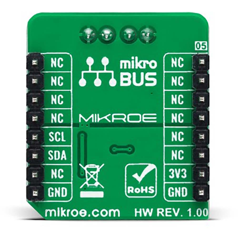
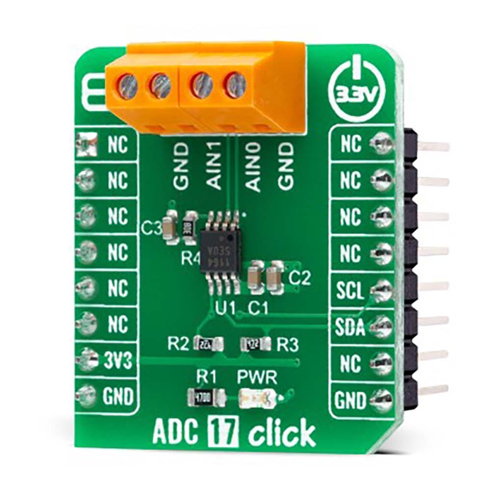
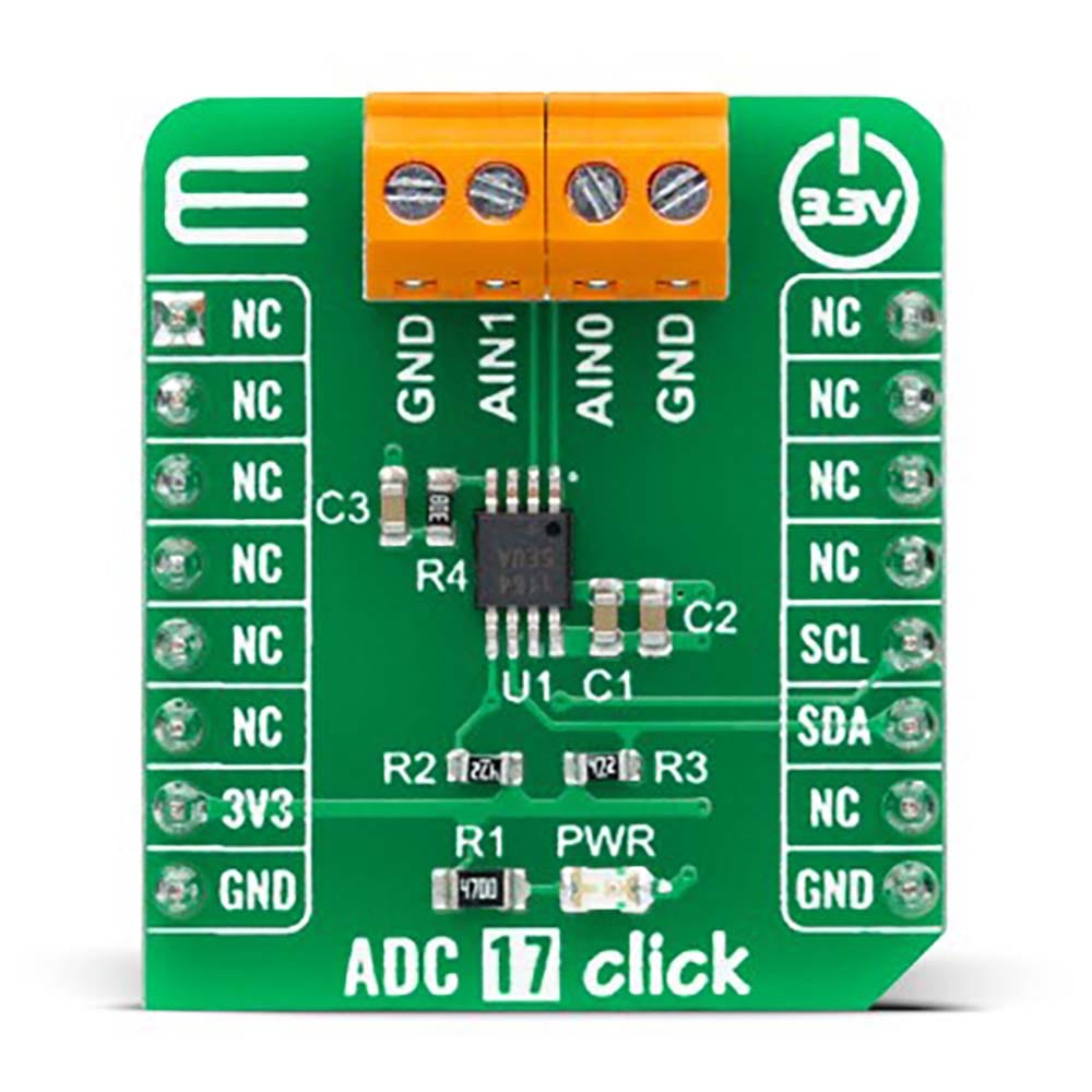
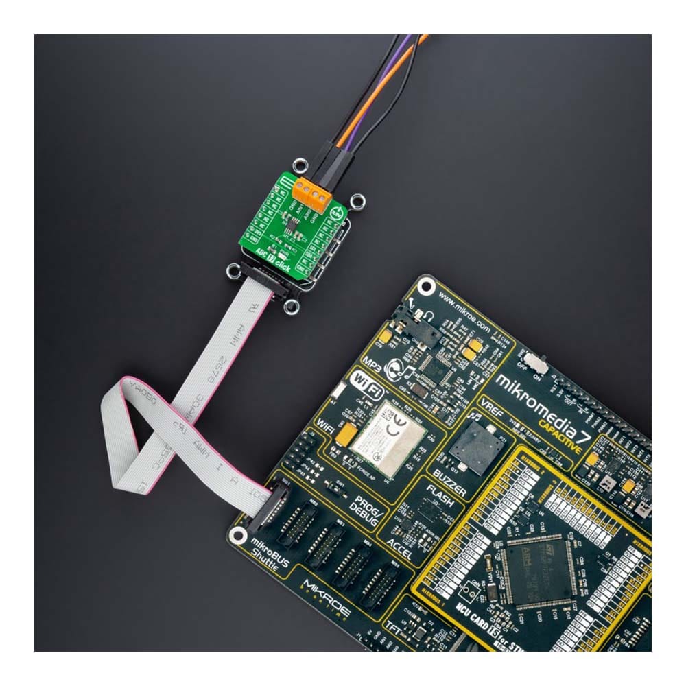
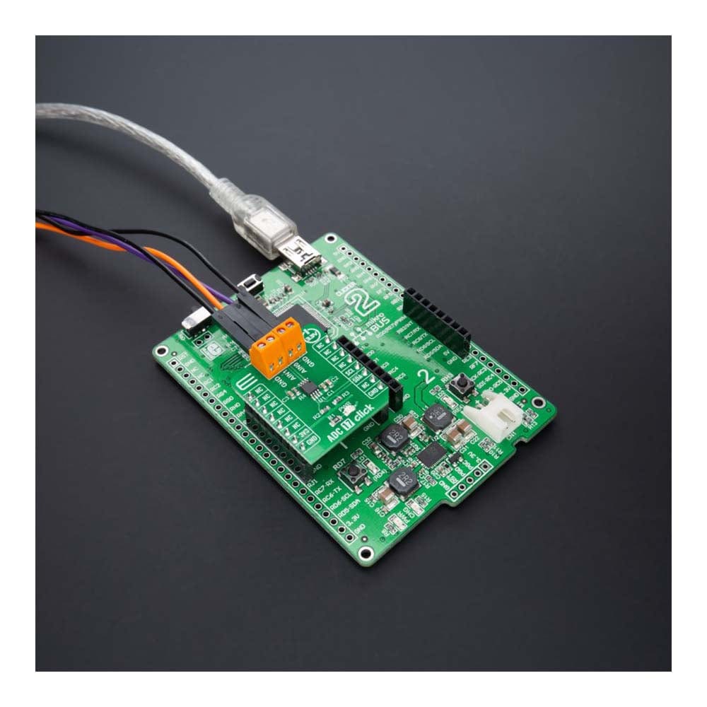
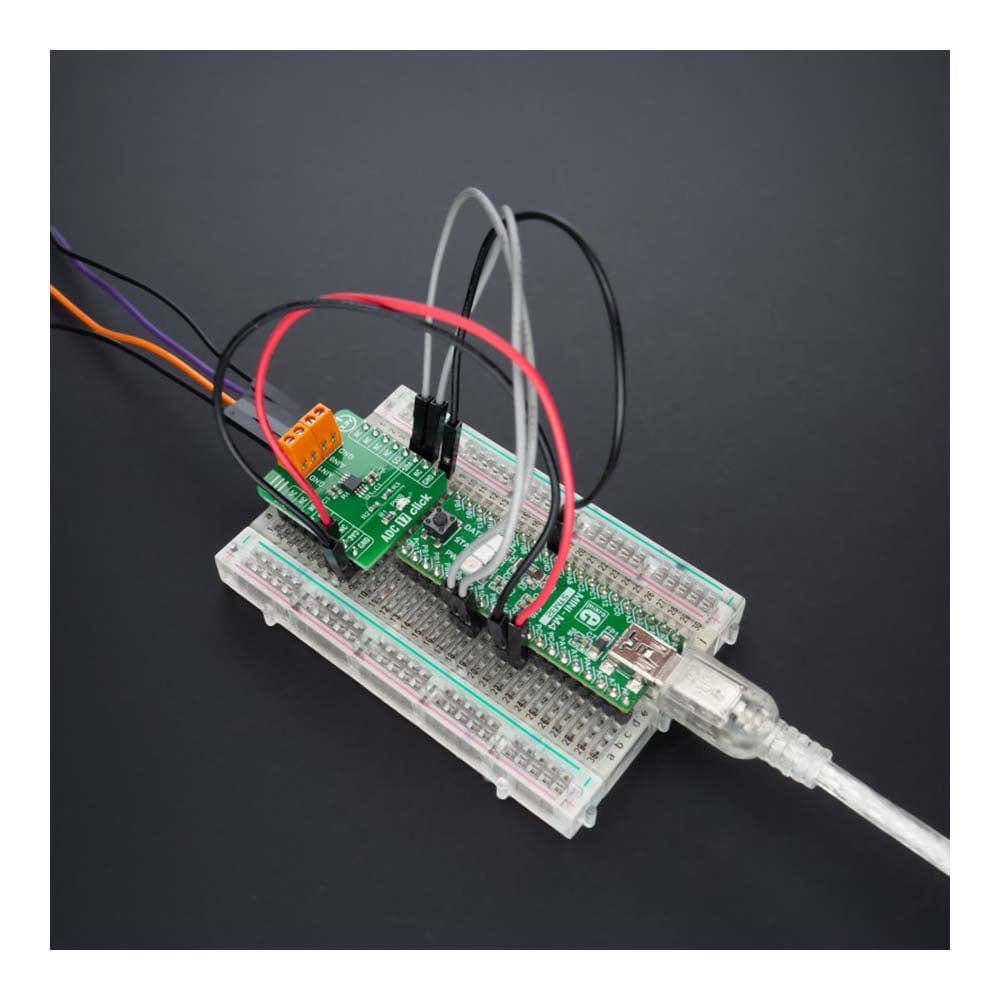
The ADC 17 Click Board™ is a compact add-on board that contains a high-performance data converter. This board features the MAX11645, a low-power two-channel 12-bit analog-to-digital converter from Analog Devices. The MAX11645 measures two single-ended or one differential input. The fully differential analog inputs are software configurable (I2C interface) for unipolar or bipolar, and single-ended or differential operation. The 2.048V internal reference determines its full-scale analog input range. This Click board™ offers complete, high accuracy solutions for the most demanding applications from energy-harvesting sensors to portable consumer electronics, point-of-load monitoring (voltage, current, and temperature), and more.
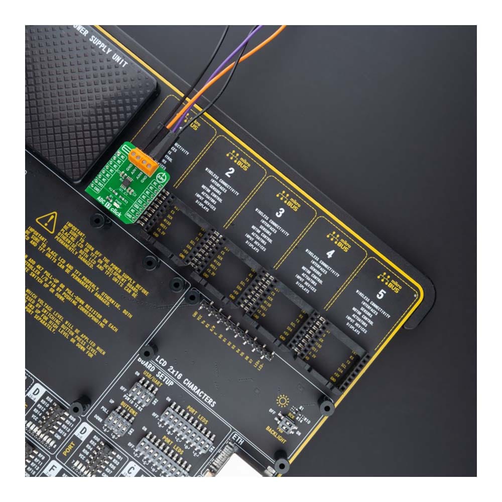
The ADC 17 Click Board™ is supported by a mikroSDK compliant library, which includes functions that simplify software development. This Click board™ comes as a fully tested product, ready to be used on a system equipped with the mikroBUS™ socket.
Downloads
Das ADC 17 Click Board™ ist eine kompakte Zusatzplatine, die einen Hochleistungsdatenkonverter enthält. Diese Platine verfügt über den MAX11645, einen stromsparenden 12-Bit-Analog-Digital-Konverter mit zwei Kanälen von Analog Devices. Der MAX11645 misst zwei unsymmetrische oder einen Differenzeingang. Die vollständig differenziellen Analogeingänge sind per Software konfigurierbar (I2C-Schnittstelle) für unipolaren oder bipolaren sowie unsymmetrischen oder differenziellen Betrieb. Die interne Referenz von 2,048 V bestimmt den analogen Eingangsbereich in vollem Maßstab. Dieses Click Board™ bietet vollständige, hochpräzise Lösungen für die anspruchsvollsten Anwendungen von Energiegewinnungssensoren bis hin zu tragbarer Unterhaltungselektronik, Lastpunktüberwachung (Spannung, Strom und Temperatur) und mehr.
Das ADC 17 Click Board™ wird von einer mikroSDK-kompatiblen Bibliothek unterstützt, die Funktionen enthält, die die Softwareentwicklung vereinfachen. Dieses Click Board™ wird als vollständig getestetes Produkt geliefert und ist bereit für den Einsatz auf einem System, das mit der mikroBUS™-Buchse ausgestattet ist.
| General Information | |
|---|---|
Part Number (SKU) |
MIKROE-4966
|
Manufacturer |
|
| Physical and Mechanical | |
Weight |
0.02 kg
|
| Other | |
EAN |
8606027389467
|
Frequently Asked Questions
Have a Question?
Be the first to ask a question about this.